
There is an UART on the Nexus 4
The Nexus 4 device features a unique architecture that allows for extensive modifications and debugging capabilities. The UART (Universal Asynchronous Receiver-Transmitter) interface is particularly valuable for developers and enthusiasts looking to engage in low-level programming and diagnostics. The circuit design described includes a comparator that operates with a reference voltage of 2.8V. This comparator serves as a threshold detector, switching its output to VCC when the input voltage exceeds the reference level, thus enabling the UART functionality.
In practical terms, the UART is connected through the headphone socket, where the RX and TX lines are assigned to specific channels (R/RX and L/TX). The configuration of the circuit ensures that when the comparator activates, audio output is disabled, allowing the UART to take precedence. The application of a bench power supply to the MIC and GND pins is critical for proper operation, with the specified voltage of 2.9V ensuring that the logic levels are correctly interpreted.
However, it is important to note that incorrect wiring can lead to component failure, as experienced during the testing phase. The mention of crosstalk on the RX port highlights the need for careful circuit design and layout to minimize interference, which can affect data integrity during transmission.
The update regarding the MIC input voltage being +3V rather than -2.9V is crucial for replicating this setup on other devices. This voltage adjustment could significantly impact the performance and reliability of the UART functionality.
For those interested in replicating or extending this project, constructing a custom cable using a 3.5mm 4-pin connector or a 3.3V USB to Serial cable with an FTDI chip could facilitate easy connectivity to various devices, enhancing the debugging experience and providing a platform for further exploration of the Nexus 4's capabilities.I chose the Nexus 4 as these devices are traditionally very open, as you can see in case of the Nexus 4 e. g. by the availability of Ubuntu Touch images. I didn`t expect however for it to be that hackable as I was about to find out on Saturday. I had just completed packaging the Mako kernel on Mer OBS in my home project and the package is now avail
able (it however doesn`t boot properly yet). So the memories from me hacking on the Archos 5 IT with the openAOS project came back and I thought, wouldn`t it be nice to have an UART available for debugging A few queries to the Internet search engine of my least distrust later I had a first lead in the form of an XDA post. This however didn`t help me much yet, which logic levels which pins really the headphone socket I quickly checked and didn`t notice anything coming out of the port when piping out /dev/urandom to /dev/ttyHSL0.
The circuit is basically a simple comparator with a reference Voltage of 2. 8V. If the input voltage on the other pin exceeds this, then it switches its output to VCC (logic 1/true). This apparently triggers a switch that turns off audio and puts a UART on R/RX, L/TX. I then proceeded to attach the bench power supply to the MIC and GND pins. (Set at 2. 9V and lowest possible current limit of about 10mA). Note that it`s connected so, that GND†’+ and MIC†’-, so -2, 9V. So, there you go, a nice and clean output. The RX port seems to suffer a bit from crosstalk though (but note the different V/div settings! for both channels!) Sadly I then connected some cables wrongly during my further experiments and it seems like I have now fried the switch.
Audio out works fine, I just can`t seem to be able to enable the UART anymore. I`m a sad panda, but at least now others can benefit from this. Update: I received some additional information. Seems it should be +3V on the MIC in after all. And this seems to also apply to other models. Anyone want to try on e. g. some of the other Nexus devices If someone wants to build a cable, here are some examples: 3. 5mm 4pin and 3. 3V USB to Serial cable based on a FTDI chip 🔗 External reference
Related Circuits
Two identical integrated circuits, U1 and U2, known as "hex inverters" are used for the theremin's primary functions. They are CMOS (Complimentary Symmetry Metal Oxide Semiconductor) devices, typically used in digital circuits to perform a logic function called "inversion."...
Electronics tutorial about quartz crystal oscillators, including harmonic, overtone, Pierce oscillator, and crystal quartz oscillator circuits. Quartz crystal oscillators are vital components in modern electronics, providing stable frequency references for a variety of applications. They utilize the piezoelectric properties of...
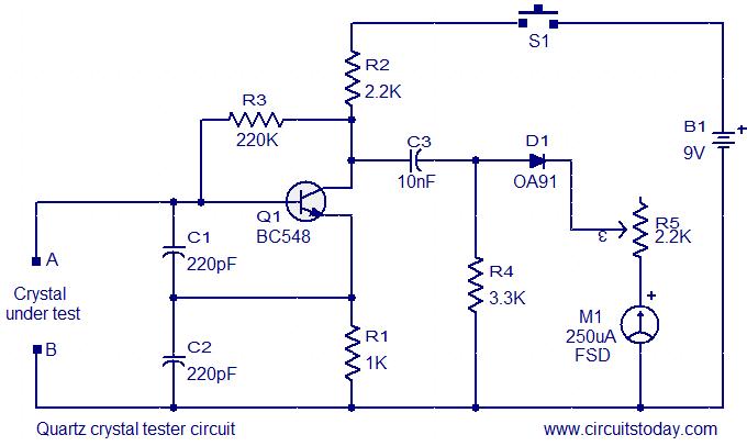
This is a straightforward and cost-effective circuit designed for testing quartz crystals. A Colpitts oscillator is employed using transistor T1. When the crystal is connected between terminals A and B, the circuit generates high-frequency oscillations. These oscillations will only...
The principle of operation of the RCA Theremin is based on the beat frequency oscillator. The frequency of one oscillator can be varied by the change in capacitance caused by the movement of the hand towards or away from...
The 203 Theremin employs Wien-bridge oscillators in a heterodyne configuration to create an audible tone that varies with hand position. It operates on a 9-volt battery, ensuring convenience and safety within a compact enclosure. This instrument is a pitch-only...
A Theremin typically operates by detecting hand proximity through the capacitive coupling method. The Theremin circuit illustrated in the schematic diagram below employs a different technique to control pitch. In this optical Theremin, the oscillator of the tone generator...