
Theremin

The next circuit to examine is the fixed pitch oscillator, which oscillates at a frequency that, when correctly adjusted, is a maximum of 1400 cycles greater than that of the variable pitch oscillator. The frequency difference is contingent upon the frequency of the variable pitch oscillator, which is determined by the hand's position relative to the pitch control rods. The frequency of the fixed pitch oscillator remains constant during play. As the hand approaches the pitch control rod, the capacitance across the pitch control circuit increases. This capacitance is reflected in the variable pitch-control oscillator, reducing its frequency. Consequently, an audible frequency difference arises between this oscillator and the fixed pitch oscillator, with the frequency of this note depending on the hand's position. As the hand nears the rod, the capacitance in the pitch control circuit increases, reducing the frequency of the variable pitch oscillator and increasing the difference between the frequencies of the two oscillators. This results in an audible note, with the note's frequency rising as the hand approaches the pitch control rod.
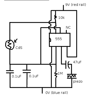
Examining the circuit diagram reveals that each oscillator grid is connected to the control and screen grids, respectively, of a Radiotron UY-224. Given that the screen grid has the largest area, a 10,000-ohm resistor is connected in series with it to balance the input to this tube and ensure each oscillator operates under similar conditions.
The RCA Theremin's design intricately combines the principles of beat frequency oscillation with capacitive sensing to create a unique and expressive musical instrument. The interaction between the user's hand movements and the electronic circuits enables real-time control over pitch and volume, resulting in a fluid and dynamic sound output. The careful tuning of the oscillator circuits, along with the strategic arrangement of components, allows for a wide range of musical expression, making the RCA Theremin a fascinating example of electronic music technology.THE PRINCIPLE of operation of the RCA Theremin is that of the beat frequency oscillator, The frequency of one oscillator may be varied by the capacity change caused in an associated circuit by the movement of the hand to or from a pitch control rod, Also an additional oscillator provides radio frequency current for heating the filament of a UX-120 arranged so as to control the volume of output, this control being due to the movement of the hand in relation to the volume control loop. A detailed description of the functioning of the various circuits follows: As stated in the foregoing, the musical note of the RCA Theremin is produced by two oscillators of slightly different frequency beating together.
This beat note is then amplified by two audio stages. The change of note caused by the movement of the hand is due to the change of capacity across what is known as the pitch coil, this slight change having sufficient effect on an adjacent oscillator circuit to change the frequency and thus the beat note, the amount of change depending on the position of the hand in relation to the pitch control rod. The pitch control rod is connected to a coil having a very high inductance. Connected to this coil is a small condenser and a small concentrated coil. This entire circuit is tuned by the distributed capacity of its coils and resonates at approximately 172 K.
C. Not having any fixed capacitor connected across it for tuning the ratio of inductance to capacitance is very high. Thus the small increase of capacity caused by the hand close to the pitch rod will cause the circuit to change its natural period considerably a great deal more than if a large capacity and small inductance were used.
This pitch control circuit is connected to the grid side of the variable pitch control oscillator, the frequency of which is slightly greater than that of the pitch control circuit. Bringing the hand close to the pitch rod will increase the parallel capacity in that circuit and thus reduce its frequency.
As this capacity is reflected in the oscillator circuit a similar decrease in frequency will result in that circuits. The amount of decrease depending. an the closeness of the frequency of the two circuits. Thus a greater decrease in frequency of the oscillator circuit is obtained when the pitch control circuit is close to the oscillator circuit in frequency than when it is a greater frequency difference.
The next circuit to examine is the fixed pitch oscillator. This circuit oscillates at a frequency, when correctly adjusted, at a maximum of 1400 cycles greater than the variable pitch oscillator. The amount of the difference is dependent on the frequency of the variable pitch oscillator the frequency of which is determined by the position of the hand in relation to the pitch control rods The frequency of the fixed pitch oscillator does not change while playing.
The hand approaches the pitch control road and increases the capacity across the pitch control circuit. This capacity is reflected across the variable pitch-control oscillator and thus reduces its frequency.
This causes an audible frequency difference between this oscillator and the fixed pitch oscillator, the frequency of this note depending on the position of the hand. Bringing the hand close to the rod will increase the capacity in the pitch control circuit, reduce the frequency of the variable pitch oscillator and increase the difference between the frequency of this oscillator and the fixed pitch oscillator.
Thus an audible note is obtained, the note increasing in frequency as the hand approaches the pitch control rod. Examining the circuit diagram we find that each oscillator gird is connected to the control and screen grid respectively of a Radiotron UY- 224.
As the screen grid has the largest area, a 10, 000-ohm resistance is connected in series with it to balance the input to this tube and have each oscillator have the sa 🔗 External reference
Related Circuits

Even if one is not familiar with the Theremin itself, it is likely that they have heard its distinctive electronic tones before. Remember those eerie soundtracks from 1950s science fiction movies? Chances are those oscillating noises were generated by...
A theremin is an instrument that can be played by changing the proximity of hands to its sensors. Traditional theremins produce classic spacey and eerie sounds commonly associated with sci-fi and horror films. The version discussed here is a...

The IR Theremin hardware schematic is notably simple, as the primary input and output devices require minimal connections. This simplicity can be a double-edged sword, as fewer hardware components often lead to increased software complexity. The main components utilized...

The CD4069 or 74C04 hex inverter is utilized as a fixed-frequency oscillator centered around 100 kHz. U2 includes the variable frequency oscillator and balanced modulator. The CD4046 functions as a phase-locked loop, with R3, R4, and C2 determining the...
As part of the National Instruments Tinker, Learn, and Do Engineering with NI myDAQ courseware, the hands-on experiments demonstrate the extensive possibilities of utilizing NI myDAQ hardware. The ten lab experiments encompass various topics, including analog and digital circuits,...
Since the publication of the type 144 theremin project article in September 1998, many of these instruments have been successfully constructed. The 145 theremin retains a heterodyne topology similar to that used in the original instruments by Mr. Theremin,...