
theremin

To create the coil, it was suggested to use a plastic film can as the coil form and number 30 enamelled magnet wire for winding. The instructions included winding 66 turns of wire in a single layer, pulling out a center tap, and continuing with an additional 33 turns. The ends of the coil and center taps were to be secured with silicone caulk. The smaller coil substitutes for the coil in Doug's oscillator, while the larger coil connects between the grid and cathode. The design remains unchanged, although the values of the variable capacitors can be adjusted to vary the oscillator frequency.
For mounting, the film can cap is attached to a piece of wood or chassis, allowing the coil to clip in place. Despite the time-consuming nature of winding these coils, the cost is minimal. The ends can be secured by looping them through holes in the can instead of using epoxy. While the 33/66 center tap configuration is not standard for a Hartley oscillator, it functions effectively, and the circuit oscillates well even with alternative tube types and lower B+ voltage. Further research led to Michael Rogers's detailed site on constructing a complete Forbes theremin, confirming the coil as Antique Electronic Supply part number P-C70-OSC, a 455KHz air-core IF transformer. Only the center-tapped side is utilized, with an inductance of 114-240uH between the outer terminals. The chassis was repurposed from a tube-based differential servo motor driver from an old analog X-Y plotter, with only the pitch section of the theremin completed. While the circuit could be made operational, tuning proved challenging due to the proximity of sensitive components, and an unusual beat frequency was observed, likely affecting the theremin's functionality.
The theremin circuit operates by utilizing two oscillators, with one oscillator's frequency being modulated by the capacitance of the player's body. The first oscillator is typically set to a fixed frequency, while the second oscillator is tuned to a frequency that varies based on the player's hand position. This modulation creates an audio frequency output that is the difference between the two oscillators. The output signal is then processed through an audio amplifier to drive a speaker, producing the characteristic theremin sound.
The construction of the coils is a crucial aspect of the theremin's functionality. The coils must be wound carefully to ensure the correct inductance values are achieved, which directly influence the oscillator's frequency. The use of a plastic film can as a coil form is advantageous due to its lightweight and non-conductive properties, which help in reducing unwanted interference. The choice of enamelled magnet wire is significant as it provides good insulation and allows for dense winding without shorting turns.
In terms of the overall design, the repurposed chassis from an analog X-Y plotter provides a sturdy foundation for the theremin. The existing power supply can be utilized, simplifying the construction process. However, care must be taken to isolate the sensitive components to prevent interference, which can complicate tuning. Adjusting the variable capacitors allows for fine-tuning of the oscillator frequencies, enabling the player to achieve the desired pitch range.
This theremin design exemplifies the integration of vintage technology with modern DIY practices, showcasing the enduring interest in electronic musical instruments and the creative potential of repurposing existing components.This was a quick experimental prototype I put together based on an elegantly simple design by Doug Forbes, which uses common vacuum tubes. (Since Mr. Forbes`s original site is no longer available I have taken the liberty of reproducing his schematic and text above.
) In its simplest form a theremin works by mixing two high-frequency oscillators, on e fixed and one tuned by the capacitance of the player`s body, and extracting the audio-frequency difference between the two signals. Typically a second capacitively tuned oscillator is used to control the amplitude of the audio output.
I had the requisite 12AU7 tubes and most of the other components already on hand, but had some difficulty finding information about the coils shown in the schematic. The solution is best summarized by this Usenet post from 2001: I`ve been working on an experimental model of this same circuit, and I was unable to find a value for the coil in question.
I believe it`s available from Antique Electronic Supply as part no. P-C70-OSC, rather than PC-70-OS as listed in the accompanying text, but didn`t want to blow $7x3 to find out otherwise. So I read through the archive of the Levnet theremin enthusiast`s mailing list and found this message pertaining to the Forbes theremin schematic: ".
Take a plastic film can-this will become your coil form. Use number 30 enamelled magnet wire (it winds very easily) and wind, in a single layer with the turns of wire laying neatly side by side, 66 turns of wire. Pull out some wire from the end of the winding (about five or six inches is fine), then with this "center tap" pulled out, continue winding an additional 33 turns of wire.
Secure the ends of the coil, and the center taps, with silicon caulk. "The smaller coil (between the center tap and the end of the 33 turns) will substitute for the coil in Doug`s oscillator between the cathode and ground, while the larger coil (the 66 turns between the beginning of the coil and the center tap) will go between the grid and the cathode. The rest of the design remains as-is, although the values of the variable capacitors can be changed to vary the oscillator frequency.
"To mount the coils, take the film can cap, and screw it to a piece of wood, the chassis, or whatever. The coil will now just "clip" in place. I`ve gotten to where I find winding coils to be very fun, and the home made type can easily sub for the hard-to-find coils shown on lots of the old plans.
" I didn`t find winding these film can coils to be so fun (it takes me about 30 min. per coil), but the cost is negligible. Rather than use epoxy I secure the ends by looping them through holes pierced in the can. It was mentioned on the list that the 33/66 center tap was not the norm for a Hartley oscillator, but however inscrutable the design choice the coils work well; the circuit oscillates like crazy, even when I sub cheap 12AX7 or 12AT7 tubes for the 12AU7s and drop the B+ voltage down to 90V or so. I later found Michael Rogers`s comprehensive site, detailing the construction of his complete Forbes theremin.
According to the information presented therein the coil is indeed Antique Electronic Supply part no. P-C70-OSC, a 455KHz air-core IF transformer, similar to Miller part no. 70-OSC. Only the center-tapped side of the transformer is used for the theremin, with an inductance of 114-240uH between the outer terminals. Please see Mr. Rogers`s site for more information than you can shake a stick at. For the chassis I reused a tube-based differential servo motor driver from an old analog X-Y plotter, with the driver circuitry removed and the power supply left intact.
Only the pitch section of the Theremin was completed. The circuit could be made to work but tuning was extremely difficult, presumably due to the many sensitive parts being in close proximity. There was also a strange beat frequency superimposed on the basic theremin function, which I suspect was
🔗 External reference
Related Circuits
This document presents a compact Theremin module designed to connect to an Arduino board, which outputs sound to a speaker or generates control signals such as MIDI or servo commands. The device serves not only as a musical instrument...
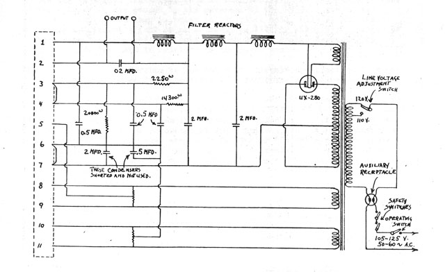
The principle of operation of the RCA Theremin is based on the beat frequency oscillator. The frequency of one oscillator can be varied by the change in capacitance caused by the movement of the hand towards or away from...
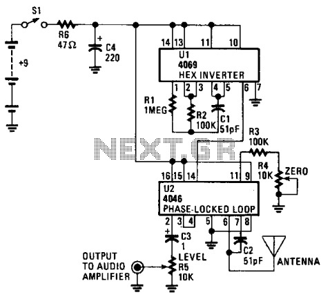
The CD4069 or 74C04 hex inverter is utilized as a fixed-frequency oscillator centered around 100 kHz. U2 includes the variable frequency oscillator and balanced modulator. The CD4046 functions as a phase-locked loop, with R3, R4, and C2 determining the...
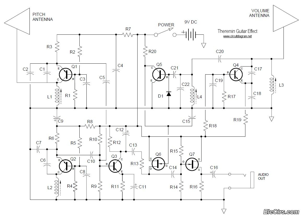
Below is the circuit diagram for the Theremin music instrument effect. A guitar or instrument amplifier is an ideal companion for the Theremin, allowing for bass or treble boost as desired, as well as fuzz (distortion) or reverberation if...
This document outlines the various sections involved in the implementation of BAMTRAT. Many component values were determined experimentally to align with personal preferences. As with constructing acoustic instruments, there is considerable scope for experimentation and customization in electronic instruments,...
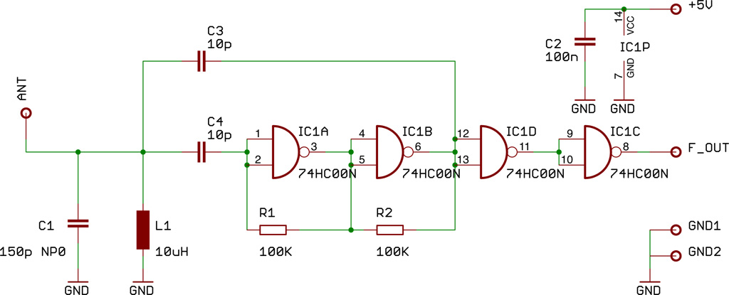
Two identical integrated circuits, U1 and U2, known as "hex inverters," are utilized for the primary functions of the theremin. These are CMOS (Complementary Symmetry Metal Oxide Semiconductor) devices commonly employed in digital circuits to perform a logic function...