
Thermally based anemometer
This action raises Al's negative input potential, leading to a decrease in Ql's emitter voltage until the circuit stabilizes at an operating point. To maintain balance in the bridge, Al adjusts to keep the lamp's resistance, and consequently its temperature, constant. The bridge values of 20 kΩ and 2 kΩ have been selected to ensure the lamp operates just below the incandescence threshold. To use this circuit, position the lamp in the airflow such that its filament is at a 90° angle to the flow. First, either stop the airflow or shield the lamp from it, and then adjust the zero-flow potentiometer to achieve a circuit output of 0 V. Next, expose the lamp to an airflow of 1000 feet per minute and calibrate the full-flow potentiometer for a 10 V output. These adjustments should be repeated until both calibration points are accurately set. Once this procedure is completed, the airflow meter can measure accurately within 3% across the entire range of 0 to 1000 feet per minute.
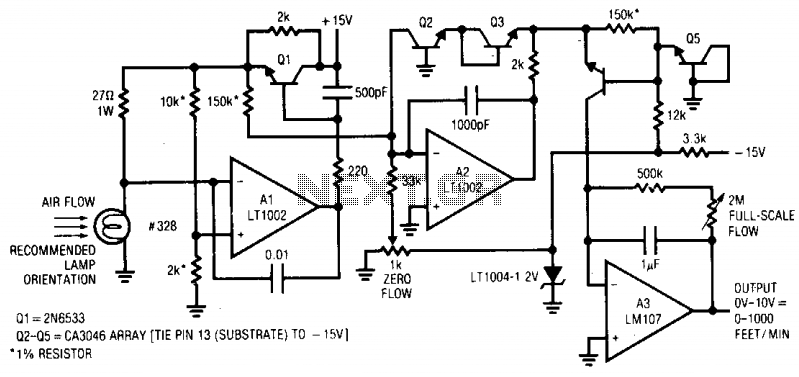
The circuit utilizes a modified type 328 lamp as a sensor, which is effective due to its positive temperature coefficient. The operational amplifier (Al) plays a crucial role in monitoring the bridge circuit and adjusting the feedback to maintain a constant temperature of the lamp. The transistor (Ql) amplifies the current output from Al, ensuring that the bridge circuit remains balanced during operation. The selected resistor values are critical in setting the operational parameters of the circuit, allowing it to function effectively just below the incandescence point of the lamp.
For practical implementation, the design requires careful calibration to ensure accuracy. The positioning of the lamp within the airflow is vital, as it must be oriented correctly to respond effectively to changes in flow rate. The zero-flow and full-flow potentiometers are essential for establishing the baseline and maximum output levels, respectively. This meticulous calibration process enables the airflow meter to deliver reliable and precise measurements, making it suitable for various applications in measuring air or gas flow rates in different environments.This design used to measure air or gas flow works by measuring the energy required to maintain a heated resistance wire at constant temperature. The positive temperature coefficient of a small lamp, in combination with its ready availability, makes it a good sensor.
A type 328 lamp is modified for this circuit by removing its glass envelope. The lamp is placed in a bridge which is monitored by Al. Al's output is current amplified by Ql and fed back to drive the bridge. When power is applied, the lamp is at a low resistance and Ql's emitter tries to come full on. As current flows through the lamp, its temperature quickly rises, forcing its resistance to increase. This action increases Al's negative input potential. Ql's emitter voltage decreases and the circuit finds a stable operating point. To keep the bridge balanced, Al acts to force the lamp's resistance, hence its temperature, constant. The 20 k - 2 k bridge values have been chosen so that the lamp operates just below the incandescence point.
To use this circuit, place the lamp in the air flow so that its filament is at a 90° angle to the flow. Next, either shut off the air flow or shield the lamp from it and adjust the zero flow potentiometer for a circuit output of 0 V.
Then, expose the lamp to air flow of 1000 feet/minute and trim the full flow potentiometer for 10 V output. Repeat these adjustments until both points are fixed. With this procedure completed, the air flowmeter is accurate within 3% over the entire 0-1000 foot/minute range.
🔗 External reference
Related Circuits
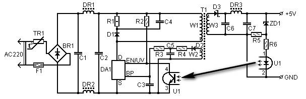
5 Volt/1.5A Switching Power Supply based on the TNY264P power supply. Refer to the designated page for an explanation of the related circuit diagram. The 5 Volt, 1.5A switching power supply utilizing the TNY264P is a compact and efficient power...
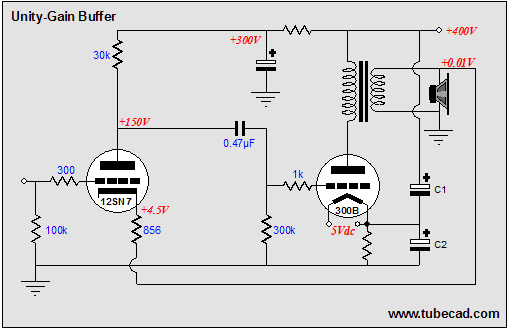
The solid-state, unity-gain power buffer is a well-known concept, but corresponding tube equivalents are less common. While super cathode followers, which are complex and augmented cathode followers with a gain of 0.99, have a long history with various designs...
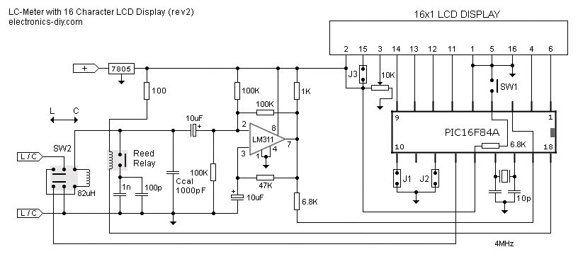
This is one of the most accurate and simplest LC inductance/capacitance meters available, which can be easily constructed by an individual. This LC meter is capable of measuring very small inductances ranging from 10 nH to 1000 nH, 1...
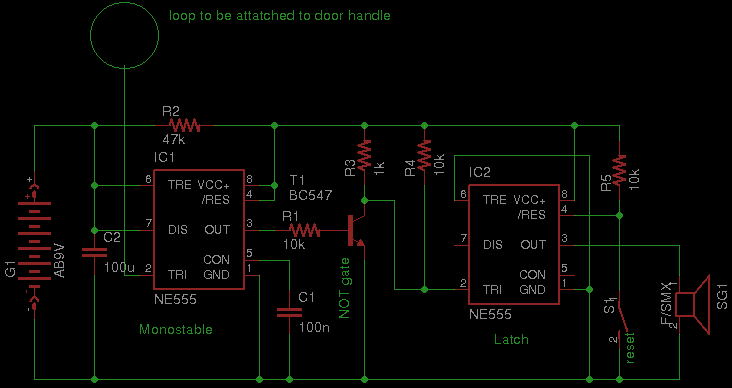
Security has become a significant concern in today's world, leading to the availability of various security gadgets. This document introduces a simple touch alarm designed specifically for doors with metallic handles. The alarm functions exclusively on metallic handles and...

The following circuit illustrates an Automatic Loudness Control Circuit Schematic. This circuit is based on the TL072 integrated circuit. Features include various functionalities. The Automatic Loudness Control Circuit is designed to adjust audio signal levels dynamically, enhancing the listening experience...
Power the frequency counter and adjust the coarse (top pot) and fine (bottom pot) controls to display zero frequency. Turn the pots counter-clockwise to achieve a zero reading. Occasionally, the counter may show only squares without digits. If this...