
thermometer

The digital thermometer circuit leverages the precision of the LM34 and LM35 temperature sensors to deliver accurate temperature readings. The LM34 outputs a voltage proportional to temperature in Fahrenheit, while the LM35 does so in Celsius, with both sensors calibrated to produce a linear output of 10 mV/°. This characteristic allows for straightforward integration with a digital multimeter, which can display temperature directly in the desired unit of measurement.
In practical applications, the assembly of the thermometer can be accomplished rapidly by using alligator clips for temporary setups, making it ideal for quick experiments. For more permanent installations, the soldering of long wires to the sensor leads enhances versatility, allowing the sensor to be placed in locations that may be difficult to access. The use of heat shrink tubing not only protects the connections but also provides a professional appearance to the final product.
The circuit diagram reveals a dual-transistor configuration where one transistor's emitter area is significantly larger than the other. This design choice results in a differential current density, which generates a voltage across resistor R1 that is proportional to the absolute temperature. The linearity of this relationship is crucial for accurate temperature measurements, and any non-linearities are corrected by additional circuitry designed for this purpose.
The amplifier circuits play a critical role in ensuring that the output voltage reflects the temperature accurately. The constant current source maintains a stable operating point for the transistors, ensuring consistent performance across varying temperatures. The compact nature of the integrated circuit allows for a highly efficient design, accommodating multiple transistors within a small footprint while providing reliable temperature measurement capabilities.
Overall, this digital thermometer design is not only effective for household experiments but also suitable for applications in incubators, terrariums, and aquariums, provided that appropriate waterproofing measures are taken. The combination of affordability, simplicity, and accuracy makes this thermometer an excellent tool for both amateur and professional use.With the easy availability of inexpensive digital multimeters, and integrated circuit temperature sensors, it is now very easy to build a sensitive and accurate digital thermometer that can be used for many experiments around the house or in the amateur laboratory. There are two tenperature sensors that make this particulary easy - the LM34 and t he LM35. These are callibrated in Fahrenheit and Celsius respectively, and when read by the meter, they produce ten millivolts per degree in their respective scales, so the meter can be directly read in temperatures, down to a tenth of a degree. Above, we have placed an LM35 sensor on top of an ice cube, and the pool of water melted from the ice is reading 8.
9 degrees Celsius. For this experiment we have simply connected alligator clips to two of the leads of the sensor, and wrapped the third lead with the red wire from the battery clip. No soldering, nothing fancy, and we have a digital thermometer in the time it takes to unwrap the meter and clip on the test leads.
For a more permanent thermometer, we solder three long wires (about 5 feet is nice) to the three leads of an LM34 Fahrenheit sensor. Use three different colors, and note which ones are attached to which leads. We put a little electrical tape around the middle lead so it won`t touch the other two, and then wrap the whole thing in electrical tape, or in this case, put it into a short length of heat shrinkable tubing, and warm it up so the tubing shrinks tightly around the whole assembly.
We made the wires long so that we can measure things inside boxes or behind doors. Five feet makes it easy to place the sensor end in the refrigerator or freezer, and have the meter stay outside where it is easy to measure. This arrangement is great for incubators for eggs, and terrariums, or (with proper waterproofing) aquariums.
At the other end of the long wires, we connect the battery clip and the resistor. Note that the wire colors help ensure that the right connections are made. In our case, the red wire from the battery clip is soldered to the brown and white striped wire, and the black wire from the battery clip is soldered to the brown wire. The brown wire is wrapped around one end of the resistor, and the blue wire is wrapped around the other end of the resistor.
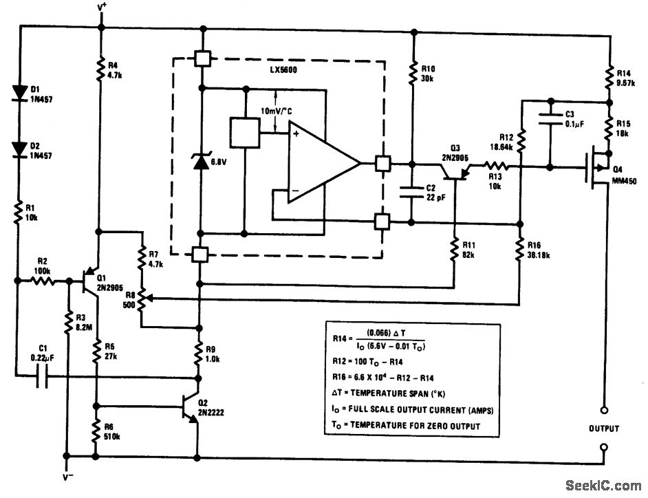
We can solder them later if we wish. In the photo above you can see how the heat shrinkable tubing makes a nice neat temperature probe, with only the top of the sensor peeking out of the shrunken tube. The circuit diagram is shown above. Briefly, there are two transistors in the center of the drawing. One has ten times the emitter area of the other. This means it has one tenth of the current density, since the same current is going through both transistors.
This causes a voltage across the resistor R1 that is proportional to the absolute temperature, and is almost linear across the range we care about. The "almost" part is taken care of by a special circuit that straightens out the slightly curved graph of voltage versus temperature.
The amplifier at the top ensures that the voltage at the base of the left transistor (Q1) is proportional to absolute temperature (PTAT) by comparing the output of the two transistors. The amplifer at the right converts absolute temperature (measured in Kelvin) into either Fahrenheit or Celsius, depending on the part (LM34 or LM35).
The little circle with the "i" in it is a constant current source circuit. The integrated circuit has many transistors in it - two in the middle, some in each amplifier, some in the constant current source, and some in the curvature compensation circuit. All of that is fit into the tiny package with three leads. 🔗 External reference
Related Circuits

The low output impedance of a closed-loop operational amplifier (op amp) provides ideal immunity to line noise, while the offset voltage drift of the op amp serves as a temperature sensor. Utilizing the op amp in this manner requires...
The output of this circuit is a current that is proportional to temperature, which can be utilized to drive a meter for direct readout. Alternatively, a resistor or operational amplifier can be employed to obtain a voltage output. The...
Function: Used to measure the voltage change minute by management before the temperature diodes. Component: IC, Diode, Resistor, 3-1/2 digit LCD (SP521PR). The circuit described functions as a voltage measurement system designed to monitor minute voltage changes, particularly in relation...
There are many digital thermometers with ±1°C displays, but their accuracy is approximately ±1°C and they cannot be calibrated. A thermometer circuit was created using components available at a local electronics hobby shop, providing an educational experience. For a...

This digital thermocouple thermometer utilizes one active component and 15 passive components. The circuit is compatible with both type J and type K thermocouples. The type J thermocouple measures temperatures ranging from 10 to 530 °C with an accuracy...
The maximum reading on the Celsius range is 199.9 °C, which is limited by the short-term maximum allowable sensor temperature. The maximum reading on the Fahrenheit range is 199 °F (93 °C), constrained by the number of display digits....