
Telephone privacy circuit
This circuit is designed to enhance telephone line management by preventing multiple telephones from being used simultaneously, thereby maintaining the integrity of calls and data connections. The primary components, the DIAC and TRIAC, play crucial roles in the circuit's operation. The DIAC serves as a voltage-sensitive switch that triggers the TRIAC when the line voltage exceeds the predetermined threshold. This allows the current to flow to the telephone, enabling its operation.
The TRIAC, on the other hand, is a semiconductor device that can conduct current in both directions when triggered. Its ability to remain in a conductive state even after the initial triggering voltage has been removed is essential for maintaining the connection until the user hangs up the phone. This feature ensures that the telephone remains functional throughout the call duration without interruption.
The circuit's simplicity is one of its key advantages, requiring only a minimal number of components, which can be easily sourced and assembled. The design allows for flexibility in component selection, particularly for the TRIAC, as long as the replacement meets the voltage and current specifications. Care should be taken when implementing this circuit, especially regarding compliance with local regulations for telephone line connections, as this design has not been type approved for public network use.
Additionally, the circuit can be adapted or modified for various applications, provided that the fundamental principles of operation are maintained. For instance, variations in the component values may be explored to optimize performance based on specific requirements or different telephone line conditions. Overall, this circuit serves as a practical solution for managing telephone line usage, providing a straightforward method to prevent unauthorized access or interruptions during calls.Built quickly from the parts found on my home lab, seemed to work on short test with telephone line simulator and line connected to PBX, I have received a report that this circuit works well in Australia This circuit is a simple circuit which prevents picking up other telephone when one telephone is in use. This can be done easily by installing this type of circuit between any telephone and the telephone line. This type of function is very useful when you don`t want other people from disturbing your modem connection or listening to your telephone calls by picking up other telephone connected to same line. The idea of the circuit is to sense the voltage in the telephone line when the telephone is picked up.
If that voltage is higher than about 30V (normal on-hook voltages is about 48V) then the circuit lets the telephone to work normally. If the voltage is lower 30V it prevents the current from going to telephone line to telehone (normally the voltage in line is about 6-10V when one telephone is off-hook).
The circuit is designed so that is passes the ring voltage to all telephones without problems. The circuit is very simple circuit built from one DIAC and one TRIAC. When telephone is picked up it will not get any operating current unless the TRIAC Q2 in series with telephone conducts. The triggering of the TRIAC Q2 is done through DIAC Q1, which will trigget the triac if there is more than about 30V voltage between TRIAC Q2 leads connected to telephone line wires.
When TRIAC Q2 start to conduct it will conduct as long as there is any current flowing through it. So TRIAC Q2 conducts until the the telehone handset is put on-hook (call has ended). This circuit is very similar to the operation of commercial adapters, but remeber that this adapter is not type approved for connection to public telephone network. The component values are just what I used in my prototype and you can replace that triac with nearly any type which will handle atleast 200V, can be triggered easily and keeps on conducting at currents as low as 15 mA.
I saw one article in sci. electronics. design which mentioned that an article in Elektor Electronics Dec/93 described a similar circuit idea. They used the following components: NOTE: The pinout of TIC206D is different than the one used in the original circuit, so the component connection drawing is different.
No wiring drawing of this modified version is available. 🔗 External reference
Related Circuits

The circuit diagram illustrates a digital precision pressure tester using the MAX1457 integrated circuit with an external ROM selection of the 93C66 type, which is a 4096-bit E2PROM. Upon powering on, the MCS pin is pulled to a high...

This design circuit is for audio graphic equalizers, which are commonly found in commercial products, yet circuits for them are rarely published. The circuit features a simple design that requires an operational amplifier (op-amp) to amplify the input signal....

The BE-150 mainframe computer features a switching power supply circuit. The circuit utilizes the oscillation control IC TIA94. A 22V voltage is supplied through the power switch S1, fuse, filter capacitor C21, L2, and a mutual inductance filter, which...
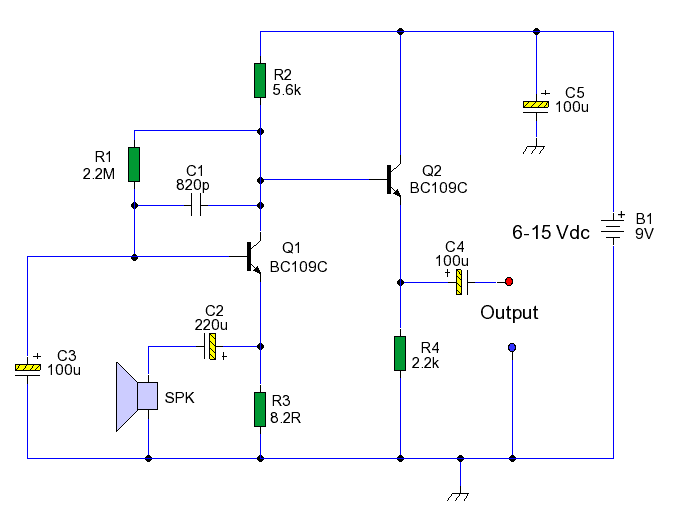
This circuit enables the use of an inexpensive loudspeaker as a microphone. Sound waves that reach the speaker cone create fluctuations in the voice coil. The movement of the voice coil within the speaker's magnetic field generates a small...

This is an AC-powered LED flasher that can drive two high-bright LEDs directly from the power obtained from the AC lines. The high-bright LED flasher can be... The AC-powered LED flasher circuit is designed to illuminate two high-bright LEDs using...
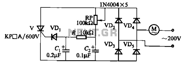
The circuit illustrated in Figure 3-11 employs a unidirectional thyristor control mechanism. An adjustable potentiometer, designated as RP, is utilized to continuously modify the motor speed. The circuit utilizes a unidirectional thyristor, also known as a silicon-controlled rectifier (SCR), which...
Warning: include(partials/cookie-banner.php): Failed to open stream: Permission denied in /var/www/html/nextgr/view-circuit.php on line 713
Warning: include(): Failed opening 'partials/cookie-banner.php' for inclusion (include_path='.:/usr/share/php') in /var/www/html/nextgr/view-circuit.php on line 713