
Thermostat Circuits
The thermostat circuit is designed to provide a cost-effective and reliable solution for temperature control applications. It typically utilizes a temperature sensor, such as a thermistor or a thermocouple, to monitor the ambient temperature. The output from the temperature sensor is fed into a comparator circuit, which compares the measured temperature against a predetermined setpoint.
When the measured temperature deviates from the setpoint, the comparator activates a control mechanism, which can be a relay or a solid-state switch, to either engage or disengage a heating or cooling element. This feedback loop ensures that the temperature is maintained within a specified range, enhancing energy efficiency and comfort.
The simplicity of the circuit design allows for easy assembly and troubleshooting, making it suitable for both hobbyists and professionals. Additionally, the use of low-cost components ensures that the overall expense remains minimal while still achieving high accuracy in temperature regulation.
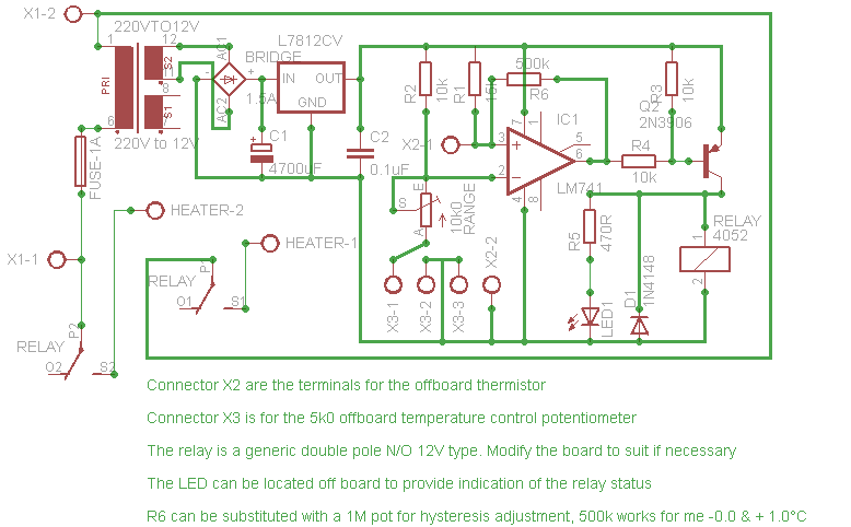
For implementation, a basic schematic would include the following components: a power supply, a temperature sensor, an operational amplifier configured as a comparator, a relay or transistor for controlling the load, and passive components such as resistors and capacitors to stabilize the circuit. Proper calibration of the temperature sensor and the comparator is essential for optimal performance, ensuring that the thermostat responds accurately to changes in temperature.
This type of thermostat circuit can be applied in various settings, including home heating systems, refrigeration units, and industrial temperature control systems, providing versatility and reliability in temperature management.Cheap, simple, and accurate thermostat circuits with instructions.. 🔗 External reference
Related Circuits
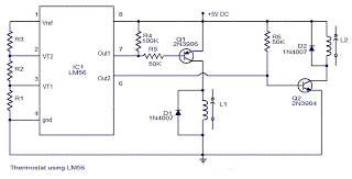
The values of the LM56 thermostat project circuit diagram for resistors R1, R2, and R3 at the travel points VT1 and VT2 can be determined using the following equations. This electronic circuit thermostat with the IC LM56 serves as...
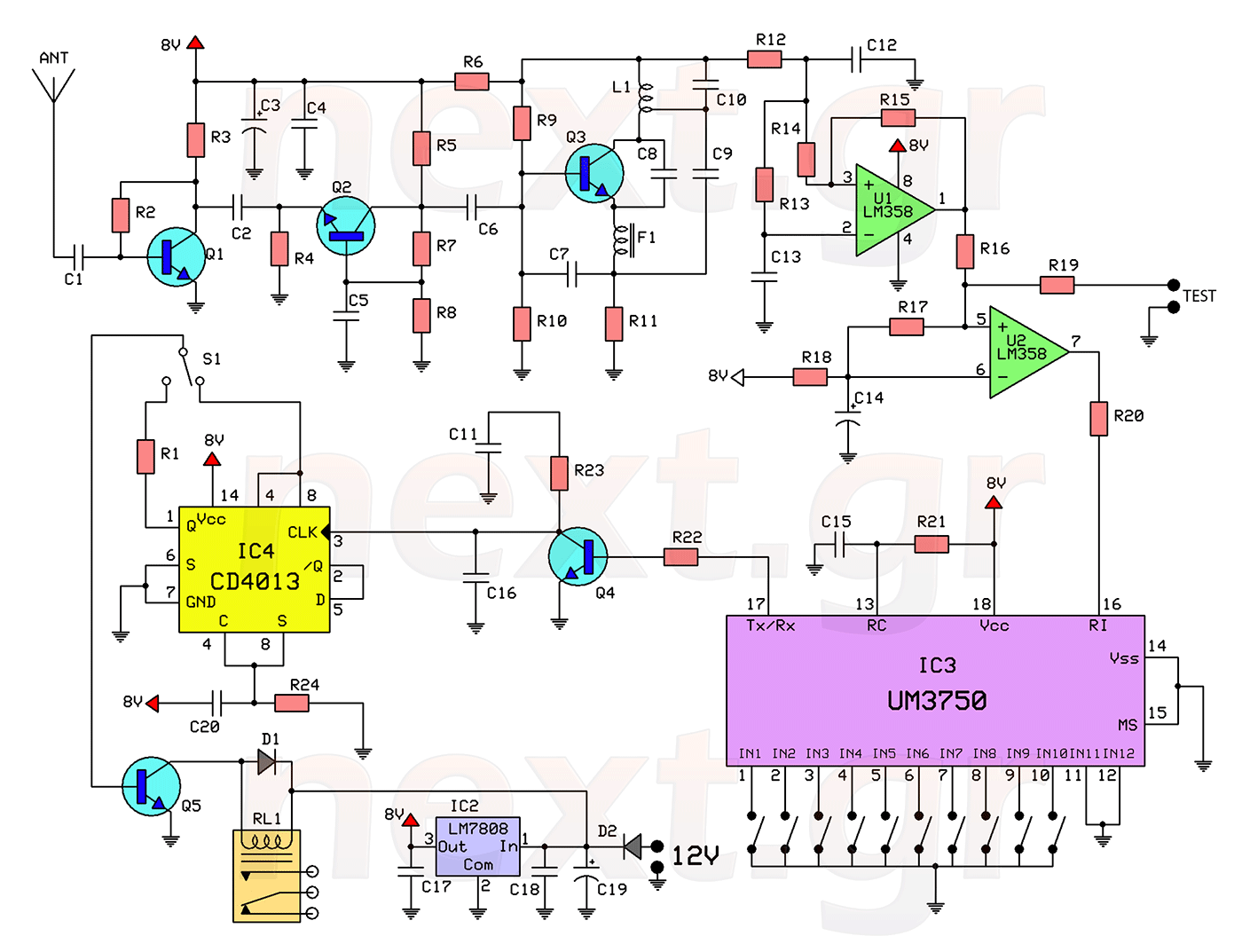
This circuit includes a 2048 radio remote control transmitter and a corresponding wireless receiver that features high reception sensitivity and low power consumption. The combination of these two components provides a highly reliable remote control system, suitable for various...
This discussion covers three different Xenon flashing circuits from disposable cameras. From these circuits, unique techniques not found in any theoretical literature will be presented. The first circuit consists of six building blocks. An old disposable flash camera and...
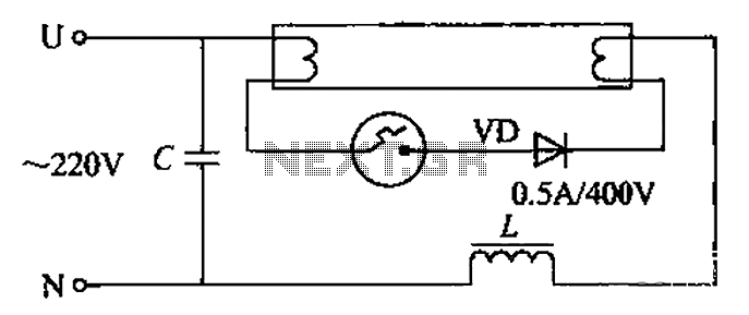
By incorporating a second pull tube into the circuit during the starter ionization phase, the positive half-cycle diode conduction results in an approximate DC current flow. This current is rectified, and due to the small ballast impedance, the instantaneous...
The following are LM555 timer circuits that have unusual functions. Designed to time a sports event; In this circuit the GREEN output is adjusted to be on for 3 minutes and then the RED output is set for 1...
Gadget Master provides the latest updates on capacitance circuits in a compilation of capacitance circuit projects and websites tailored for electronics designers, scientists, and engineers. Capacitance circuits are fundamental in various electronic applications, serving critical roles in timing, filtering, and...