
THREE INPUT VIDEO MIXER
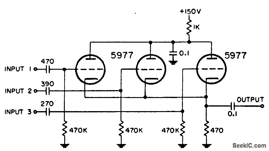
In radar systems, the integration of various signal components is crucial for accurate data representation and operational effectiveness. The described circuit serves as a versatile combination unit that allows for the merging of three specific inputs: radar video, beacon signals, range markers, range strobe, and azimuth markers. Each of these components plays a significant role in enhancing the radar system's functionality.
Radar video provides the primary visual information about detected objects, while beacon signals are essential for identifying specific targets or areas of interest. Range markers and range strobe signals assist in determining the distance to objects, contributing to the overall situational awareness. Azimuth markers indicate the direction of targets, which is vital for navigation and targeting applications.
The circuit is likely designed to handle analog signals, ensuring minimal distortion during the combination process. It may incorporate operational amplifiers for signal amplification and mixing, along with filters to eliminate unwanted noise. The selection of components would be critical to maintain signal integrity, especially in high-frequency applications typical of radar systems.
Furthermore, the circuit may include adjustable parameters to prioritize certain signals over others, allowing for flexibility based on operational requirements. This adaptability is essential in dynamic environments where the radar system must respond to varying conditions and threats.
Overall, this combination circuit is a fundamental element in radar technology, facilitating the effective integration of multiple signal types to enhance the performance and reliability of radar systems in various applications.Used in radar systems for combining any three of the following: radar video, beacon, range markers, range strobe, and azimuth markers. -NBS, "Handbook Preferred Circuits Navy Aeronautical Electronic Equipment, " Vol. 1, Electron Tube Circuits, 1963, p N4-1. 🔗 External reference
Related Circuits

The following method allows the timer to be triggered by a normally closed switch. This would be useful in applications such as intrusion alarms where the protection circuit is broken if a window or door is opened. Trigger Input...
The video amplifier illustrated in the diagram represents a well-established design that is simple yet highly effective. However, there is a risk of damaging the transistors if the potentiometers, which control black level and signal amplitude, are set to...
Incorporate resistors in a parallel configuration to enhance audio input. To control the volume for each input channel, integrate a linear trimmer or potentiometer with the following configuration: pin 1 connects to ground, pin 2 serves as the output,...
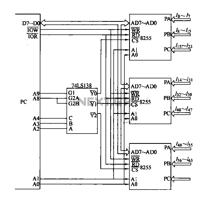
The computer control system is designed to detect signal path switching, requiring multiple input interface expansions. This system can switch all signal inputs into the computer. By utilizing a programmable chip, the 8255 expansion input interface allows for three...
The objective of this project was to design a compact, portable mixer powered by a 9V PP3 battery while maintaining high-quality performance. The mixer consists of three primary modules that can be adjusted in number and configuration to meet...
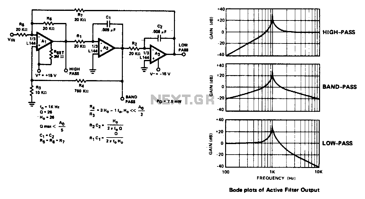
The active filter is a state variable filter with bandpass, high-pass, and low-pass outputs. It is a classical analog computer method of implementing a filter using three amplifiers and only two capacitors. The state variable filter is a versatile circuit...