
Three-Level Audio Power Indicators
The audio output power indicator circuit is designed to visually represent the power level of an audio amplifier through the use of three light-emitting diodes (LEDs). Each LED corresponds to a specific range of output power, providing a clear and immediate visual cue of the amplifier's performance.
The circuit typically operates by monitoring the output voltage of the amplifier. A voltage divider may be employed to scale down the output voltage to a manageable level suitable for the LED driver circuit. The LEDs are then connected to a comparator or a series of comparators that are configured to turn on at predetermined voltage thresholds.
For instance, the first LED may illuminate at low power levels, indicating safe operation, while the second LED activates at a medium power level, suggesting that the amplifier is approaching its limits. The third LED lights up at high power levels, alerting the user to potential overdrive conditions.
To ensure accurate operation, resistors are used to limit the current flowing through each LED, preventing damage and ensuring longevity. Additionally, capacitors may be included in the circuit to filter any noise from the power signal, providing a more stable and reliable indication of output power.
This circuit can be integrated into various amplifier designs, enhancing usability by providing real-time feedback on audio output levels. It is an effective tool for audio enthusiasts and professionals alike, allowing for better management of amplifier performance and preventing potential damage due to overdriving.This circuit indicates audio output power via three LEDs. Nice addon to your amplifier.. 🔗 External reference
Related Circuits
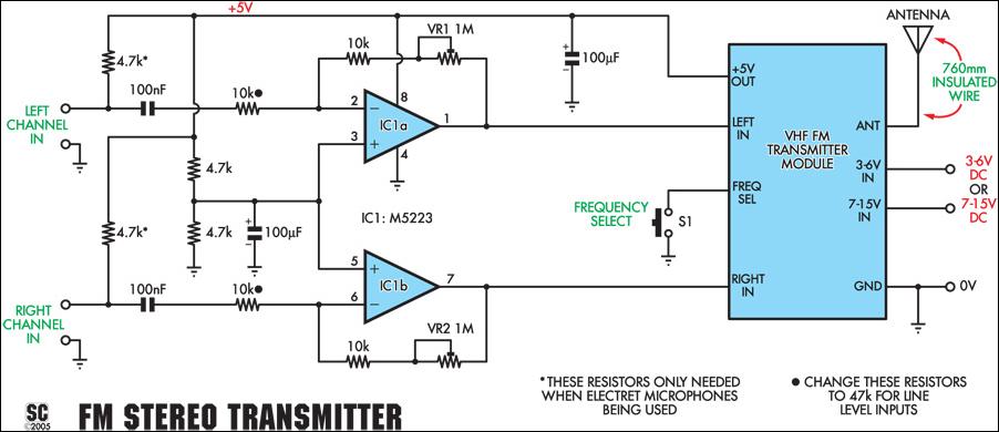
This stereo FM wireless microphone provides a high-quality audio link. It has been tested successfully over a distance of 50 meters, demonstrating solid performance. This wireless microphone distinguishes itself by offering stereo sound with impressive audio quality. Additionally, it...
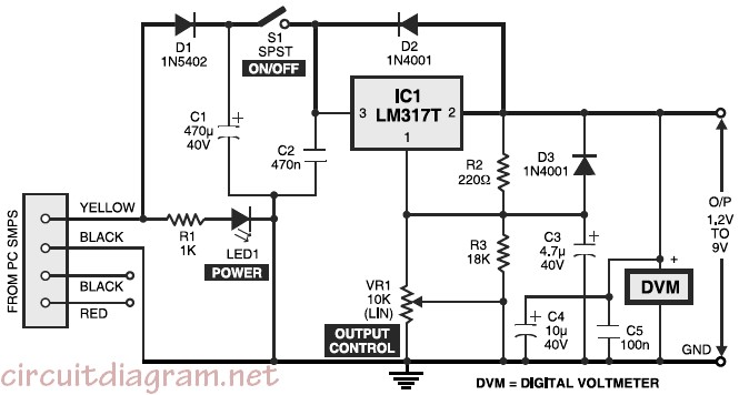
Variable desktop power supply that converts a high input voltage (12V) from the SMPS/PSU of a desktop computer into a small output voltage (1.25V to 9V). The variable desktop power supply is designed to provide adjustable output voltages ranging from...
This solid-state push-pull single-ended Class A circuit is designed to deliver sound quality comparable to valve amplifiers, providing an output power of 6.9W measured across an 8 Ohm loudspeaker cabinet load. It features reduced total harmonic distortion (THD), increased...
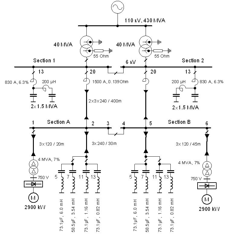
The vertical line indicates the instance of the 5th harmonic filter connection. The diagram illustrates the power system with the designed group of single-tuned filters for a system with a DC drive supplied by a 6-pulse controlled rectifier: PN...
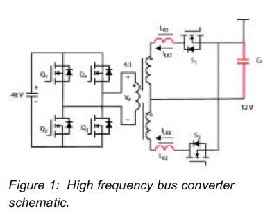
This article demonstrates that enhancement mode GaN transistors facilitate substantial efficiency enhancements in resonant topologies and provides a practical example of wireless power transmission. Enhancement mode Gallium Nitride (GaN) transistors are semiconductor devices that have gained attention for their ability...
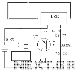
The circuit operation principle of the device illustrated in Figure 13 is as follows: When the barbed wire (Fe) remains intact, the output pin (O) of the LSE is at a high state. Consequently, the transistor (VT) remains off,...
Warning: include(partials/cookie-banner.php): Failed to open stream: Permission denied in /var/www/html/nextgr/view-circuit.php on line 713
Warning: include(): Failed opening 'partials/cookie-banner.php' for inclusion (include_path='.:/usr/share/php') in /var/www/html/nextgr/view-circuit.php on line 713