
Three-phase ac motor driver 2
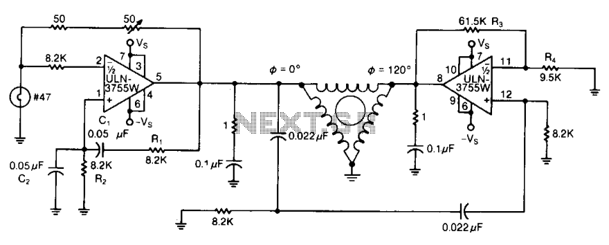
The circuit described involves a frequency-adjustable oscillator that utilizes resistive components R1, R2, R3, and R4 to manipulate frequency and gain characteristics. The oscillator's frequency can be finely tuned through the adjustment of resistors R1 and R2, which are part of the timing network. By altering these resistors, the time constant of the oscillator circuit can be modified, thereby changing the frequency of oscillation within a specified narrow range.
The feedback mechanism in the oscillator includes two amplifiers, where the gain of the second amplifier is determined by the ratio of resistors R3 and R4. This gain adjustment is crucial for compensating for any signal loss that may occur within the phase shifters, ensuring that the output maintains integrity and desired amplitude levels.
Furthermore, the circuit has the capability to be externally driven by a pulse or square wave source. This feature allows the left-hand amplifier's gain to be set lower than the threshold required for self-oscillation, effectively stabilizing the circuit and preventing unwanted oscillations when external signals are applied.
The inclusion of RC feedback networks serves a dual purpose: they not only contribute to the overall feedback necessary for oscillation but also act as active filters. This filtering action is essential in shaping the output waveform, transforming it from potentially distorted signals into smooth sinusoidal outputs. The result is a well-defined oscillation that is suitable for various applications, including signal processing, waveform generation, and modulation tasks in electronic systems.By varying either Rl or R2, the oscillator frequency can be adjusted over a narrow range. The R3/R4 ratio sets the second amplifier's gain to compensate for signal attenuation occurring in the phase shifters. The circuits can be driven from an external source, such as a pulse or square wave, setting the gain of the left-hand amplifier to a level less than that required for oscillation.
The RC feedback networks then function as an active filter causing the outputs to be sinusoidal. 🔗 External reference
Related Circuits
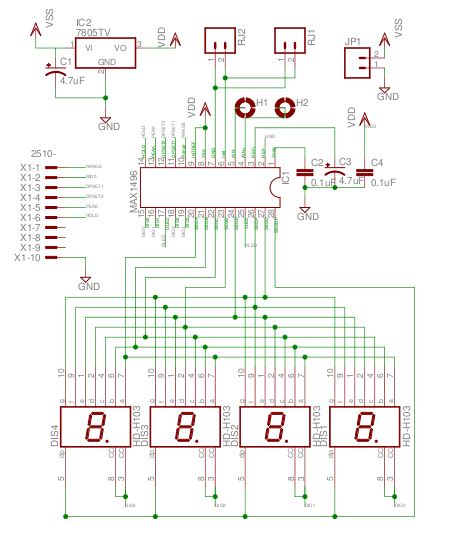
The MAX1496 is an analog-to-digital converter (ADC) that incorporates LED drivers, allowing for the construction of a 3 1/2 digit voltmeter using a minimal number of components. This device features both external and internal voltage reference options, along with...
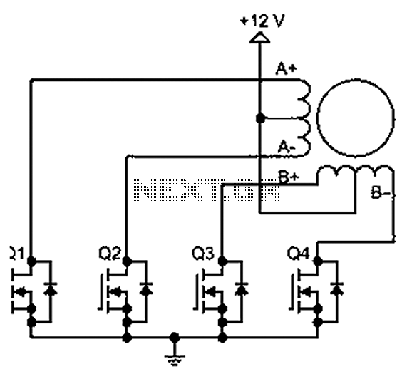
A bipolar stepper motor drive circuit is presented, utilizing eight transistors to operate two phases. This bipolar drive circuit can accommodate both four-wire and six-wire stepper motors; however, it is primarily designed for four-wire bipolar configurations, which can significantly...
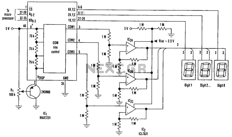
Large LCD devices with one or more displays exhibit significant driving capacitance to the driver circuits. To address this issue, the drive circuit incorporates a buffer amplifier for each of the three common lines. Each amplifier can be programmed...
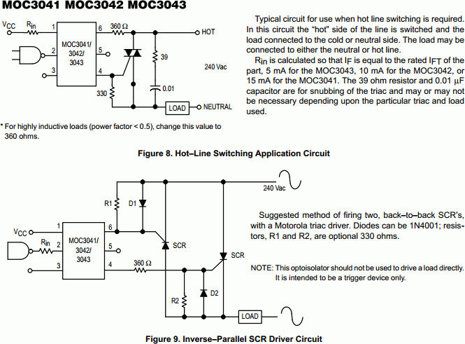
The MOC303XM and MOC304XM devices consist of an AlGaAs infrared emitting diode optically coupled to a monolithic silicon detector, functioning as a zero voltage crossing bilateral triac driver. They are designed for use with a triac in the interface...
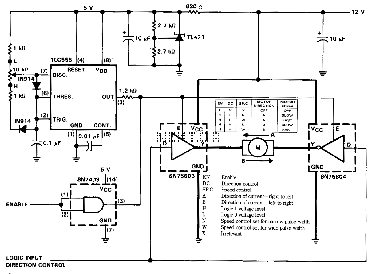
The figure illustrates a reversible DC motor drive application with adjustable speed control. The D inputs for these drivers are complementary and can be tied together and driven from the same logic control for bidirectional motor drive. The enables...
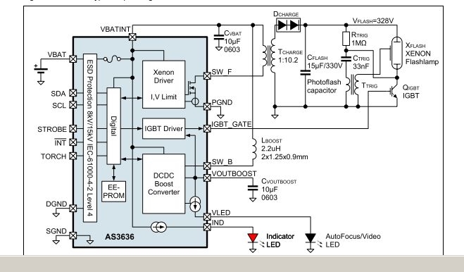
The AS3636 is a highly integrated photoflash charger that includes an IGBT driver, an inductive DC-DC boost autofocus/video LED driver, an indicator LED driver, and incorporates system-level ESD protection. The AS3636 is designed for efficient photoflash charging applications, providing a...
Warning: include(partials/cookie-banner.php): Failed to open stream: Permission denied in /var/www/html/nextgr/view-circuit.php on line 713
Warning: include(): Failed opening 'partials/cookie-banner.php' for inclusion (include_path='.:/usr/share/php') in /var/www/html/nextgr/view-circuit.php on line 713