
Bipolar stepper motor drive circuit diagram

The bipolar stepper motor drive circuit operates by controlling the current flow through the motor phases, allowing for precise positioning and speed control. The circuit consists of eight transistors arranged in pairs to create two H-bridge configurations, one for each phase of the motor. Each phase can be energized independently, enabling full-step or half-step driving modes, which enhance the resolution of the motor's movement.
In a typical implementation, the microcontroller sends control signals to the lower transistors of each H-bridge, effectively switching them on and off to create the desired current flow through the motor coils. The upper transistors, which are connected to a higher voltage supply, provide the necessary current to the motor when the lower transistors are activated. This configuration allows for efficient control of the motor's operation while minimizing power loss.
The choice of a bipolar configuration over a unipolar design offers several advantages, including higher torque and better efficiency due to the full use of the motor windings. Additionally, the absence of a clamping circuit simplifies the design and reduces component count, making it suitable for cost-sensitive applications.
For protection and performance enhancement, it is advisable to include flyback diodes across the transistors to manage voltage spikes generated when the motor phases are switched. This ensures the longevity and reliability of the circuit. Proper heat dissipation methods, such as heat sinks or thermal pads, should also be considered to prevent overheating of the transistors during prolonged operation.
Overall, the bipolar stepper motor drive circuit is an effective solution for driving stepper motors in various applications, providing a balance of performance, cost efficiency, and simplicity in design. Bipolar stepper motor drive circuit is shown, it will use eight transistors to drive two phases. Bipolar drive circuit can drive four-wire or six-wire stepper motor, although t he motor can only use four-wire bipolar drive circuit, it can significantly reduce the cost of high-volume applications. The number of transistors bipolar stepper motor drive circuit is twice the unipolar drive circuit, wherein the lower end of the four transistors are usually driven directly by the microcontroller, the upper transistor is a cost higher upper drive circuit.
Bipolar transistor drive circuit only withstand voltage of the motor, so it is not a unipolar drive circuit as required clamping circuit.
Related Circuits
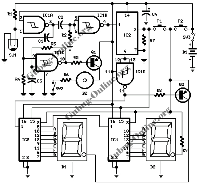
This design features a signal logic tester that utilizes a common cathode seven-segment display. The display indicates a logic level "1" (represented by an "H" on the display) or a logic level "0" (represented by an "L" on the...
This circuit provides a digital square wave that can be viewed directly or used to drive other circuits. It used the CMOS 4047 Low-Power Monostable/Astable Multivibrator. As used in Tom Duncan's Adventures with Digital Electronics Book, to drive CMOS...
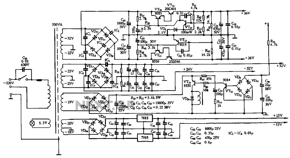
The power supply circuits for servo systems are critical during both the adoption and operational stages. The power supply circuit for servo systems is designed to provide stable and adequate voltage and current levels necessary for the servo motors to...

This circuit is a simple telephone ringtone generator designed using minimal components. It produces a simulated telephone ringing tone and operates on a DC voltage ranging from 4.5V to 12V. This circuit can be utilized in standard intercom systems...
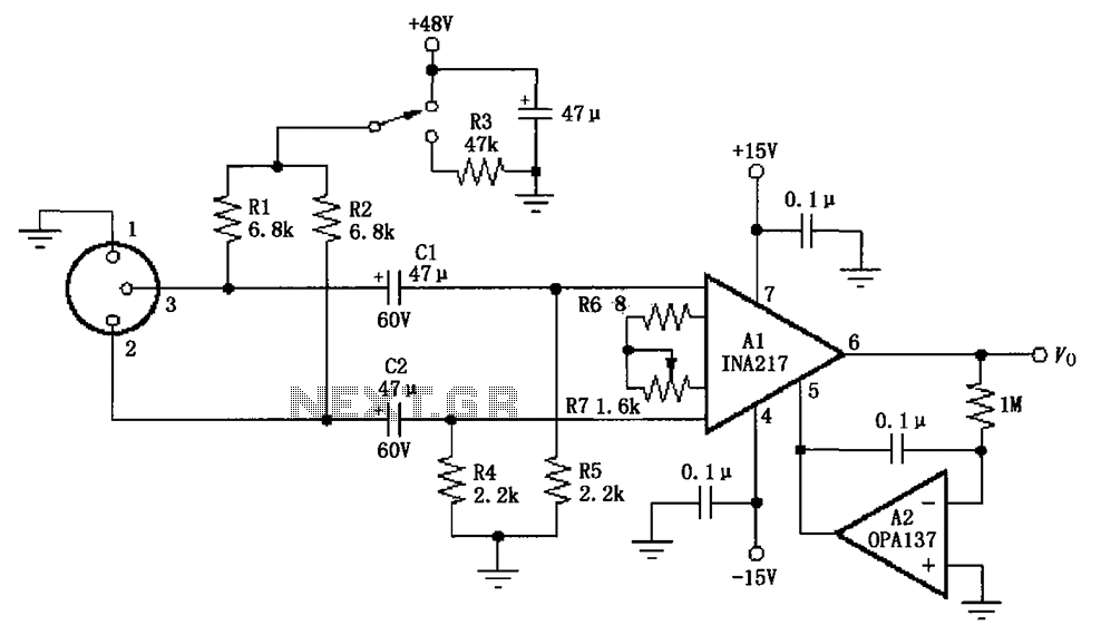
The circuit depicted in the figure consists of an INA217 professional miniature microphone preamplifier. A switch is included to select the use of phantom power. When the switch is connected to +48V, phantom power is enabled; if the switch...
This circuit outputs a voltage of 14 volts with a maximum current of 4A. It can be used for NiCad batteries and accumulators, both wet and dry types. However, the accumulator must be rated for 12 volts and have...