
thyristor
Thyristors are integral components in various electronic applications due to their unique ability to control current flow with precision. Their three-terminal structure allows for versatile integration into circuits where controlled rectification is necessary. In power electronics, they enable efficient conversion and management of electrical energy, making them suitable for use in applications ranging from motor control to power supplies.
The thyristor's ability to remain in a conducting state without continuous gate activation presents advantages in applications where power efficiency is critical. For instance, in coilgun designs, the thyristor facilitates rapid discharge of energy stored in capacitors, enhancing performance by delivering high peak currents to the coil. This characteristic is particularly beneficial in pulsed power applications, where precise timing and control over energy delivery are paramount.
In protective circuitry, thyristors serve as crucial elements in surge protection systems. By quickly responding to voltage spikes, they safeguard sensitive components from damage, thereby enhancing the overall reliability of electronic systems. The design of thyristor-based protection circuits often includes strategic placement of resistors and diodes to manage voltage levels and prevent unwanted current flow, ensuring that the circuit operates within safe parameters.
Overall, thyristors are versatile and essential components in modern electronics, providing reliable control over electrical power and protecting sensitive circuits from transient disturbances. Their application in various fields demonstrates their importance in advancing electronic technology and improving system performance.A thyristor is like a diode; it can pass electricity in a forward direction but, blocks it in a reverse direction. The difference between a diode and a thyristor is that the thyristor is a three terminal device consisting of an anode, cathode and gate, which will also block current flow in the forward direction until it`s gate is signaled to open
or, to use more technical jargon, the thyristor is fired . Once turned on, the gate signal is removed and the thyristor remains on until the current through it drops to zero, which conveniently happens during each cycle of the main supply. Thyristors are most commonly known as Silicon Controlled Rectifiers (SCRs), Triacs, Thyristor Surge Protective Devices & SIDACs, and Programmable Unijunction Transistor (PUT).
Although it can take many forms, they all have certain things in common. Normally-off switches, a small current pulse into the gate electrode can trigger thyristors on . Once triggered, the component then stays in the conducting state even when the gate on signal is removed. It only returns to the off (blocking) state if the current falls below a certain minimum or if the direction of the current is reversed.
The circuit symbol is shown below. When there is no gate current, the device is in the non-conducting state and will hold off positive and negative bias voltages. The zero gate current characteristic is: Coilgun Thyristors are the device of choice when using a basic capacitor discharge coilgun.
The thyristor will hold off the capacitor voltage until it is triggered into the forward conduction zone by the gate current signal. The capacitor then discharges through the thyristor into the coil and the current decays to zero. There is no option for turning off the current once the device is conducting. *Coilguns have no industrial application use* Despike ac lines (snubber circuit) Alternating current transmission lines are susceptible to spikes.
Using thyristors on the primary side of a transformer eliminates spiking. The purpose of using thyristors to despike the voltage (dv/dt) is for enhanced controllability. Historically, replacement of mercury-arc valves by thyristors yielded robust ac/ dc converters, minimized conversion losses, and yielded fast control on transmitted power ”so much so that line-to-ground fault clearing became possible without the use of circuit breakers. Instead, by rapidly attaining zero current through the use of current controllers and, in addition, by rapidly recovering the electromagnetic energy stored in the energized line, the faulted dc line could be isolated by low interruption rating isolators.
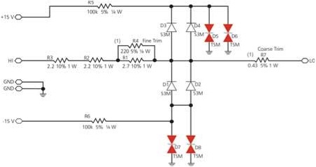
To wit, if the voltage rate of rise is great enough (high enough), the thyristors will turn on controlling the current without interruption. Shown in the schematic, the thyristors are kept at the edge of conduction, which respond in nanoseconds to limit the spike passed into the instrumentation amplifier inputs to a few volts.
As the thyristors conduct, the voltage is dropped across resistors R1-4. The use of these thyristors protects circuits to limit the damaging effects of errant high-energy pulses resulting from either test equipment or ICD malfunction. The solution is a set of energy-absorbing circuits set to shunt voltages of more than 16 V quickly, while minimally loading the circuit.
Shunting is performed by thyristors D5-8. To ensure quick action and minimal capacitive loading, they are held at a bias voltage near their trigger point by supply rails at +15 V and -15 V. The back-biased diodes D1-4 isolate the rails from the circuit under normal conditions and prevent leakage current in the thyristors from loading the signal line.
These protection circuits are applied on sensitive circuits to divert unintentional energy (spikes). Without them, the reliability of the interface would be in question after any failure of an ICD under test. A similar but simpler protection circuit 🔗 External reference
Related Circuits
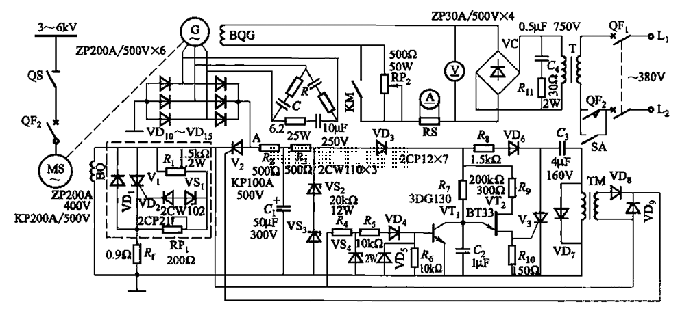
The circuit depicted in Figure 16-105 illustrates a synchronous motor. The components include BQ, which represents its field winding, and G, which denotes the AC excitation for the motor. The notation BQG indicates the field winding, with an empty...
The silicon controlled rectifier (SCR), commonly referred to as a thyristor, functions similarly to a diode. When the cathode is negative relative to the anode, current can flow. The silicon controlled rectifier (SCR) is a semiconductor device that plays a...
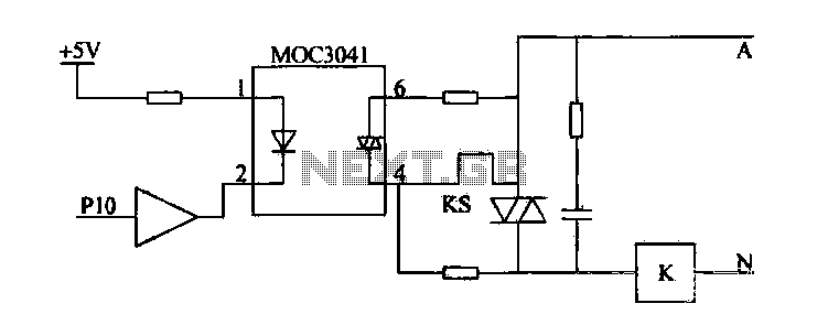
Device for an intermediate relay. The circuit utilizes a Triac AC contactor interface, employing the MOC3041 Triac output optical coupler to trigger the Triac. When Pl0 is low, the Triac will be activated, energizing the AC contactor coil. The described...
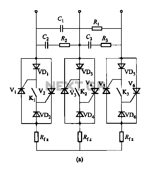
Figure 16-48 (a) illustrates the introduction of a six thyristor three-phase AC switching circuit, while Figure 16-48 (b) depicts the implementation of three triac circuits. These configurations are suitable for motors and other inductive loads. The six thyristor three-phase AC...
The circuit receives its input from the zero-crossing detector, which generates a 0-to-1-to-0 pulse to set the R-S flip-flop and activate the ramp circuit (A to Ramp) to initiate the timing ramp ascent. The described circuit operates by utilizing a...
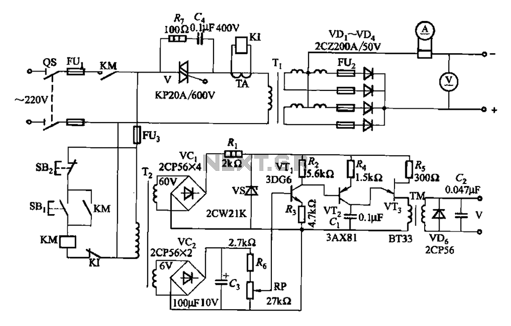
A 500A-6V single-phase power supply circuit designed for thyristor electroplating. This circuit can output a continuous DC current of 500A at 6V, which is adjustable for plating processes. It incorporates a single-junction transistor as part of the trigger circuit,...