
Basic Thyristor Switch

The silicon controlled rectifier (SCR) is a semiconductor device that plays a crucial role in controlling power in electronic circuits. It is a four-layer, three-junction device that can be turned on by applying a small gate current, allowing it to conduct current between the anode and cathode when a specific voltage threshold is surpassed.
In its off state, the SCR behaves like an open switch, blocking current flow. When a positive gate pulse is applied, the device transitions to its on state, allowing current to flow from the anode to the cathode. The SCR remains in this conducting state until the current flowing through it falls below a certain threshold, known as the holding current.
SCRs are widely used in applications such as phase control in AC power circuits, motor speed control, and in rectifiers for converting AC to DC. They are favored for their ability to handle high voltages and currents, making them ideal for industrial applications. Their characteristic switching behavior can be exploited in various power electronics circuits, including inverters, converters, and regulators, enabling efficient energy management and control.
In a typical circuit schematic involving an SCR, the device is represented by a symbol that includes three terminals: the anode (A), cathode (K), and gate (G). The gate terminal is connected to a control circuit that provides the necessary trigger signal to turn on the SCR. Protection components such as snubber circuits may also be included to safeguard against voltage spikes and transients, ensuring reliable operation in demanding environments.
Overall, the SCR is a versatile component in modern electronics, providing efficient control over electrical power in a wide range of applications.The silicon controlled rectifier (S.C.R.) is called as the thyristor. It is like a diode, when the cathode is negative with respect to the anode, the current.. 🔗 External reference
Related Circuits
A simple test circuit designed for troubleshooting audio and radio equipment. It can inject a square wave signal rich in harmonics or be used with headphones as an audio tracer. A single-pole double-throw switch is utilized to toggle between...
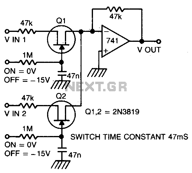
Two or more signals can be switched and/or mixed without annoying clicks by using FETs and a low input-impedance op amp circuit. The circuit design utilizes Field Effect Transistors (FETs) to facilitate the switching and mixing of multiple signals while...

Four 4.8 Volt 2000mA Nickel Cadmium batteries require a safe method for initial charging using a lab power supply, as a specific NiCad charger is not available. Assistance is sought for circuit drawings of a simple NiCad charger. The...
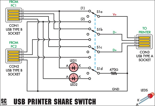
This device allows two computers to share a single USB printer or other USB devices, such as an external flash drive, memory card reader, or scanner. A rotary switch is used to select the PC that will use the...
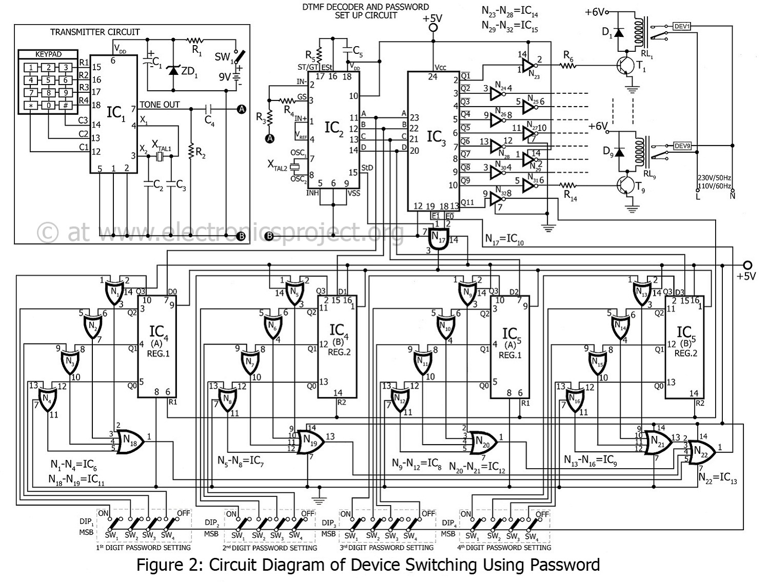
This project involves device switching using a password, developed by the innovative group Dreamlover Technology. It allows users to lock their devices with a password. The block diagram of the device switching system is presented in figure 1. The...
It is often necessary to control electrical appliances remotely, even when there is no direct line of sight between the transmitter and receiver. In modern electronic applications, remote control systems are increasingly utilized for various purposes, including home automation, industrial...