
Simple Dc/Ac Inverter Circuit
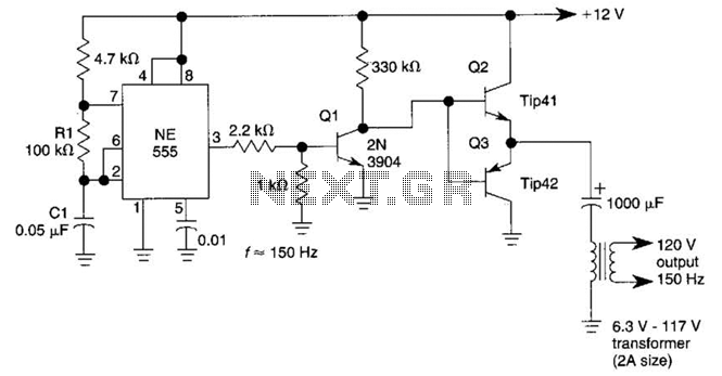
The circuit functions by converting direct current (DC) into alternating current (AC) using the 555 timer as an oscillator. The 555 timer is configured in astable mode, generating a square wave output that oscillates between high and low states. This output drives the buffer amplifier, where transistors Q1, Q2, and Q3 amplify the signal to a suitable level for driving the transformer.
The choice of transformer T1 is critical, as it determines the output voltage and current characteristics of the inverter. A 6.3-V transformer is typically used for low-power applications, while a 12.6-V transformer can be employed for higher power needs. The output frequency of the inverter is predominantly determined by the timing components R1 and C1. By adjusting these components, the user can fine-tune the frequency to match specific requirements of the load being powered.
The design of this inverter is advantageous for applications requiring low-cost and lightweight solutions for AC power generation from a DC source. It is commonly used in small electronic devices, battery-operated equipment, and other applications where a compact inverter is necessary. The simplicity of the circuit allows for easy troubleshooting and modifications, making it a popular choice among hobbyists and engineers alike. This dc-to-ac inverter is based on the popular 555. A 555 oscillator circuit drives a buffer amplifier consisting of Ql, Q2, and Q3. The circuit operates at 150 to 160 Hz. Tl can be a 6.3-V or 12.6-V filament transformer as applicable. The frequency can be changed by changing the values of Rl and/or Cl. 🔗 External reference
Related Circuits
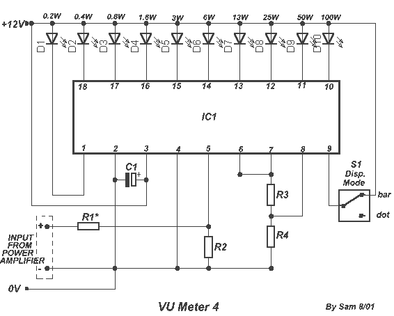
The circuit is placed parallel with the exit of power amplifier and gives the level of signal from output. Changing resistance R1 in the input circuit, we adapt the indication of power in the resistance of loudspeaker that we...
It was observed that balls were becoming lodged in the ball trough, failing to load into an upkicker or not resting correctly on the trough ball microswitches or optos, which caused the machine to register a missing ball. Initially,...
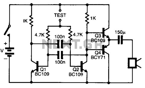
The pitch of the tone is dependent upon the resistance under test. The tester will respond to resistance of hundreds of kilohms, yet it is possible to distinguish differences of just a few tens of ohms in low-resistance circuits....
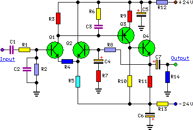
To complement the 60 Watt MOSFET audio amplifier, a high-quality preamplifier design was necessary. A discrete components topology using +24V and -24V supply rails was chosen, minimizing the transistor count while still achieving low noise, very low distortion, and...
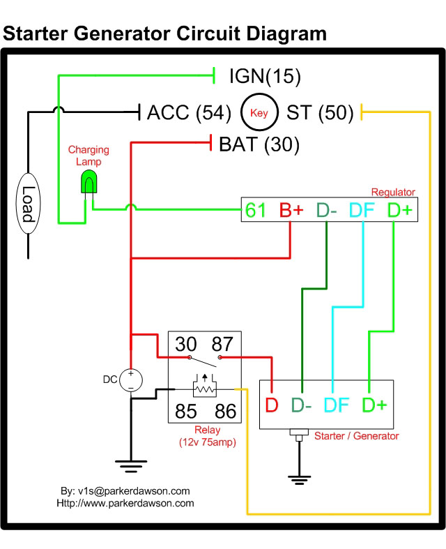
Circuit diagrams for both a Bosch and a Delco-Remy Starter-Generator are available, noting that the circuits differ. Due to a computer crash, the original diagrams and the associated email address were lost. However, in May 2004, both the email...
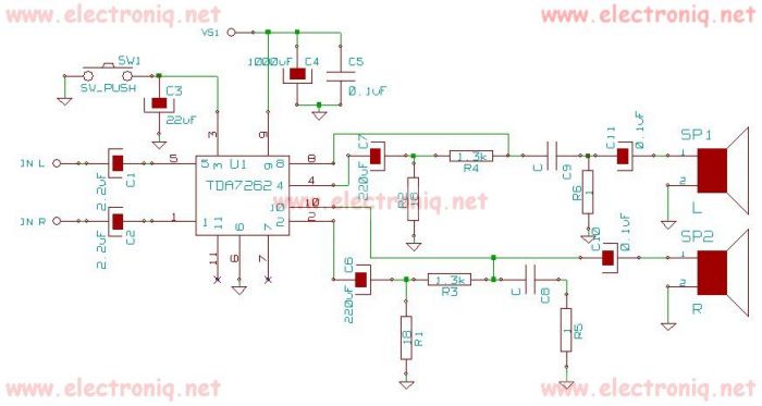
TDA7262 stereo 20 watts audio amplifier circuit design electronic project The TDA7262 is an integrated circuit designed for stereo audio amplification, capable of delivering up to 20 watts per channel. This amplifier circuit is suitable for various applications, including home...