
TiDiGino the Arduino-based GSM remote control
The TiDiGino system, leveraging the capabilities of the ATmega 2560 microcontroller, offers a versatile platform for remote control applications. The integration of GSM technology enables users to remotely manage devices, making it suitable for various automation tasks. The inclusion of DTMF signaling allows for easy control via telephone, while the dual input/output configuration enhances the system's flexibility. The design accommodates expansion through standard shields, promoting versatility and ease of integration with existing Arduino projects.
The firmware development approach encourages user engagement, allowing individuals to customize their solutions based on specific requirements. By providing the necessary libraries and example sketches, users can quickly get started with their projects, reducing the learning curve associated with GSM integration. Furthermore, the requirement for an external power supply ensures that the system operates reliably under different conditions, making it suitable for both indoor and outdoor applications.
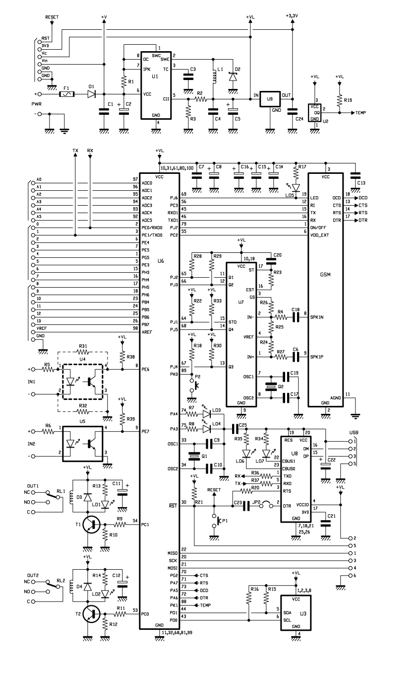
In summary, the TiDiGino project exemplifies a well-thought-out design that combines robust hardware with user-friendly software, fostering innovation within the Arduino community while addressing the growing demand for remote control solutions.Using an ATmega 2560 and therefore the heart of Arduino, we have developed a universal remote control with GSM. This allows to control 2IN/2OUT, DTMF key, gate control and GSM thermostat activated remotely. The remote control is easier, thanks to the availability of several libraries that allow you to do anything to the Arduino microprocessor; if
there is not really a specific library, you can modify an existing one. Thus was born TiDiGino, based on the chip ATmega 2560 used in Arduino Mega. Our system has connectors S. I. L. to mount any shield, each of them is in the same location where you would be in the original development platform, which enables the use of commercial and in any case the standard shield. We said that the functions of our remote control, ie 2IN/2OUT, gate opener, key DTMF GSM and thermostat can be achieved by using special firmware, well, we could write these ourselves, but we wanted to offer our readers who know the Arduino environment do them.
This is the sense of TiDiGino Contest, which you could follow our blog and that has just ended, as promised, we publish the hardware of the remote control and a few routines. The TiDiGino is based on a ATmega 2560chip, some pins are used to manage GSM functionality, corresponding to ports that are not used in the original Arduino MEGA.
For this reason it is necessary to replace the file pins_arduino. c located under the folder C:ProgramFilesarduino-0022hardwarearduinocoresarduino that is created by downloading the Arduino IDE, with that we made available with the library, otherwise it is possible to manage all`ATmega 2560 lines of I/O provided by the platform Arduino MEGA. This choice was intended to leave some I/O free for use by any shield. Therefore you can use the sketches already made to control a specific shield with the original Arduino board, even on TiDiGino.
To test the circuit we made four sketches, each of which allows you to use a section of the system. The sketches are all contained in the file GSM_TDGINO. zip, downloadable from the development page of Google, which contains the library that allows you to manage the GSM of TDGINO. This library comes from the one developed by HWKitchen, but has been adapted to our hardware, as, for example, use the second serial dell`ATMEGA2560 to manage the GSM module of Simcom SIM900.
Decompressing the zip in the folder of the Arduino libraries (eg C:ProgramFilesarduino-0022libraries) the library is immediately usable. By copying the library, are also automatically installed the examples we have developed to manage the various sections, in order to test these examples must be connected to the USB port TDGINO and provide an external power supply circuit of about 12 VDC (1 A of current).
This creates a virtual COM will be used to program the remote control. Select the Board Arduino Mega 2560 ³ and from File-> Examples-> GSM_TDGINO, choose the example that you want to upload to the remote control. 🔗 External reference
Related Circuits
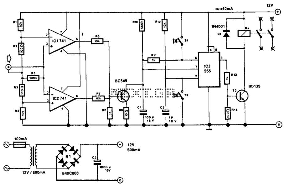
This circuit will disconnect the line supply to audio or video equipment if there has been no input signal for approximately 2 seconds. Switch SI provides manual operation, while switch S2 functions as a reset mechanism. This circuit allows...
Instructions for constructing and utilizing a basic PIC programmer using readily available and inexpensive components. The total cost for building the programmer is under $1.50. The simple PIC programmer is designed to facilitate the programming of PIC microcontrollers, which are...
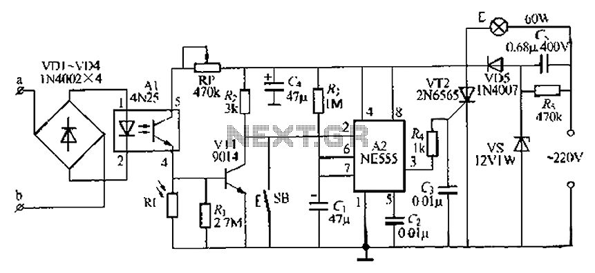
The lamp base circuit integrates an NE555 timer and optocouplers to automatically activate the light when a phone call is received at night. The lamp will self-extinguish after a delay. Additionally, a switch allows manual control of the lamp....
The 555 oscillator operates with a +12V supply and ground, without the need for a -12V supply. The 555 timer IC is a versatile component commonly used in various oscillator and timer applications. In this configuration, the circuit is powered...
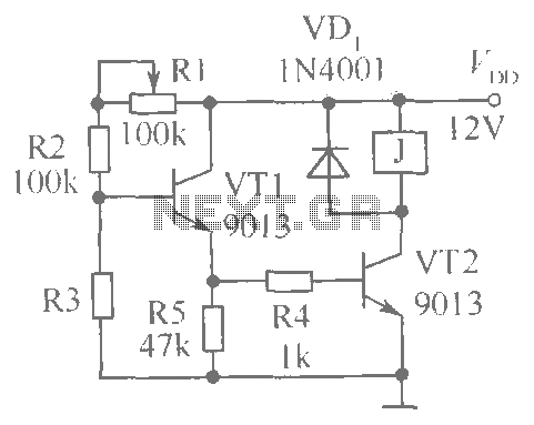
This document presents a brightness control relay circuit. Resistors R1, R2, and R3 create a voltage divider circuit with a light-sensitive resistor. When the light level drops below a specific threshold, the base voltage of VT1 increases, causing VT1...
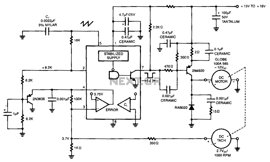
The NE5561 provides pulse-proportional drive and speed control based on DC tachometer feedback. This simple switching circuit consists of a 2N4920 PNP transistor with a commutation diode, which is used to deliver programmed pulse energy to the motor. A...
Warning: include(partials/cookie-banner.php): Failed to open stream: Permission denied in /var/www/html/nextgr/view-circuit.php on line 713
Warning: include(): Failed opening 'partials/cookie-banner.php' for inclusion (include_path='.:/usr/share/php') in /var/www/html/nextgr/view-circuit.php on line 713