
Stylus sand acoustic filter circuit diagrams
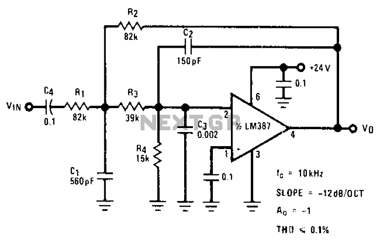
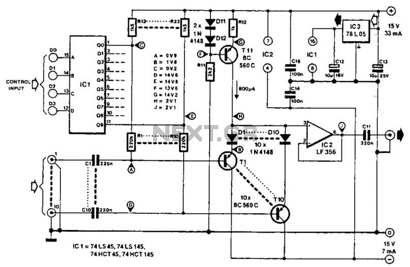
This circuit operates as a low-pass filter, effectively attenuating frequencies above the specified corner frequency of 10 kHz. The design typically incorporates an operational amplifier (op-amp) configured in a non-inverting setup to achieve the desired gain of 1. The low-pass filter characteristics can be implemented using passive components, such as resistors and capacitors, arranged in a first-order filter configuration.
In this circuit, the input signal is fed into the non-inverting terminal of the op-amp, while the feedback network, consisting of a resistor and capacitor, determines the cut-off frequency. The corner frequency (fc) can be calculated using the formula:
fc = 1 / (2πRC)
where R is the resistance in ohms and C is the capacitance in farads. By selecting appropriate values for R and C, the circuit can effectively filter out unwanted high-frequency noise while allowing lower frequency audio signals to pass through unaffected.
In practical applications, this circuit can be utilized in audio processing systems, such as mixers, amplifiers, or recording equipment, where the elimination of high-frequency noise is essential for achieving clean audio output. Additional considerations include power supply requirements for the op-amp and proper grounding techniques to minimize noise interference in the circuit. Circuit offers passband gain 1,10kHz corner frequency for eliminating high frequency noise such as hiss, ticking, popping sound.
Related Circuits
The circuit was quickly assembled from components available in a home lab and performed well during initial tests using a telephone line simulator and a line connected to a PBX. Reports indicate that this circuit functions effectively in Australia....

The schematic for this project is designed to be very simple, utilizing a minimal number of components to keep costs and assembly time low. The primary components in the schematic include the PIC 18F452 microcontroller, a tilt sensor, and...
Audio light modulations add to the enjoyment of music during functions organised at home or outdoors. Presented here is one such simple circuit in which light is modulated using a small fraction of the audio output from the speaker...
The TBA120 Series integrated circuits (ICs) offer a high-gain limiting intermediate frequency (IF) amplifier and a quadrature coincidence detector in a single package. These ICs are primarily designed for the extraction of television intercarrier sound, which is frequency modulated...
This circuit employs switched emitter followers instead of conventional analog switch CMOS chips, resulting in a more effective reduction of crosstalk between channels. It can manage up to 4 Vms with less than -80 dB crosstalk. The circuit design utilizes...
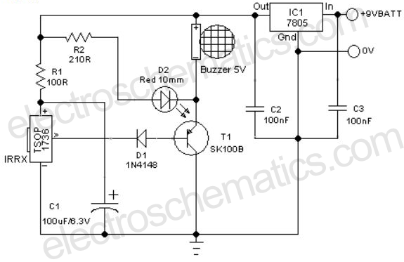
A remote-controlled alarm circuit utilizing the TSOP1736 is designed for easy use by elderly individuals or patients confined to bed. This battery-operated alarm system eliminates the need for routing electric cables to a calling bell switch, making it a...