
33kW and above windlass with Y- transfer power-saving circuit

The circuit design for a windlass rated at 33 kW and above incorporates a Y-conversion power-saving mechanism. This design is crucial for optimizing the efficiency of the windlass, which is commonly used in marine applications for anchoring and mooring vessels.
The Y-conversion circuit enables the windlass motor to operate in a star (Y) configuration during startup, which reduces the initial inrush current and minimizes voltage drops in the system. Once the motor reaches a certain speed, the circuit can switch to a delta (Δ) configuration, allowing the motor to utilize its full power capacity for heavy lifting and hauling operations.
Key components of the circuit include contactors for switching between the Y and Δ configurations, a control relay to manage the transition based on motor speed, and protection devices such as circuit breakers to prevent overloads. The circuit may also incorporate a soft starter to further reduce mechanical stress and electrical surges during startup.
This power-saving circuit not only enhances the operational efficiency of the windlass but also contributes to energy conservation, making it an essential feature for modern marine equipment. Proper implementation of this circuit can lead to significant cost savings in energy consumption and improved performance in demanding marine environments.33kW and above windlass with Y- conversion power-saving circuit
Related Circuits

Caution! This strobe light circuit operates on 220V, making measurements and experiments extremely hazardous, even after disconnecting it from the mains. The strobe light circuit is designed to produce high-intensity flashes of light at specified intervals. It typically consists...

A negative temperature coefficient thermistor is utilized as the temperature sensing element (Rt). The circuit includes a resistor (Ri), a resistor (Rs), a potentiometer (RP), and the thermistor (R) to form a temperature bridge. A differential amplifier is created...

This RFIC amplifier operates in the 2400 MHz ISM band and features a two-stage design that is off-chip matched to ensure optimal performance across various applications. Powered by a 5-volt supply, the PM2107 can deliver 1 watt of saturated...
The following circuit diagram depicts a variable power supply controlled by a PIC microcontroller. An LCD display is utilized to show the actual output current and voltage values. This digital power supply incorporates a push-button switch to adjust the...
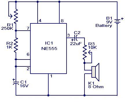
This weblog focuses on electronic circuit schematics, PCB design, DIY kits, and diagrams for electronic projects. A simple circuit utilizing the NE555 IC is presented, which can be employed to generate metronomes. This circuit is particularly beneficial for music...

A 12V car battery is recommended as the input for this circuit, utilizing the 2N3055 transistor as the amplifier. This configuration can deliver a power output of up to 100W, making it suitable for use in battery chargers, emergency...