
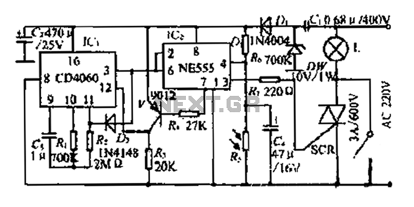
time delay relay
A time delay relay circuit typically includes several key components: a timer IC (integrated circuit), resistors, capacitors, and the relay itself. The timer IC, such as the 555 timer, is often configured in monostable mode to create the desired delay. Upon activation, the timer begins counting based on the RC (resistor-capacitor) time constant, which is determined by the values of the resistor and capacitor connected to it.
The adjustable timing feature is achieved by using a variable resistor (potentiometer) in conjunction with a fixed resistor and capacitor. By varying the resistance, the time delay can be finely tuned to meet specific requirements. The output of the timer IC is connected to the relay's coil, which energizes the relay when the timer completes its countdown.
The relay used in this circuit can be selected based on the application's current and voltage requirements. For example, a standard electromagnetic relay can handle higher loads, while a solid-state relay may be used for faster switching and lower power applications.
It is essential to ensure that the relay's specifications match the load it will control, as this will determine the overall current capacity of the time delay relay circuit. Proper heat dissipation and protection components, such as diodes for flyback protection, should also be included to safeguard the circuit from voltage spikes generated when the relay is deactivated.
In conclusion, a time delay relay circuit provides a reliable solution for applications requiring a delayed response, allowing for flexibility in timing and load control.A time delay relay is a relay that stays on for a certain amount of time once activated. This time delay relay is made up of a simple adjustable timer circuit which controls the actual relay. The time is adjustable from 0 to about 20 seconds with the parts specified. The current capacity of the circuit is only limited by what kind of relay you decide to use.. 🔗 External reference
Related Circuits
This timer is designed for individuals seeking to achieve a tan while minimizing excessive exposure to sunlight. A rotary switch adjusts the timer based on six classified photo-types. A photoresistor modifies the preset time according to the brightness of...
A photosensitive daytime electricity circuit utilizes a very small positive voltage. It features a 555 timer IC with four pins, including a reset pin that operates at low voltage. The circuit includes a bidirectional thyristor (iSCR) that controls lighting,...
In the Fig.1, there exists a circuit, which is a sensitive switch that responds to AC signals of input, for signals above 5mV. It responds to all the signals from 50 Hz to 3 kHz, a region in which...
This device is designed to maintain a deep cycle battery using energy harvested from a solar panel. It functions as a combination of a digital clock timer and a solar panel charge controller. Component: .. This circuit serves the dual...
This is a driving relay circuit utilizing a 555 integrated circuit (IC). The circuit is designed to control a relay and prevent the 555 IC from becoming unresponsive by employing inductive feedback. The coil is safeguarded. The driving relay circuit...
Below are three examples of controlling a relay from the PC's parallel printer port (LPT1 or LPT2). Figure A shows a solid state relay controlled by one of the parallel port data lines (D0-D7) using a 300 ohm resistor...