
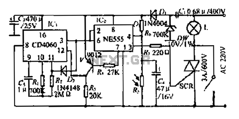
A long delay light control lighting controller circuit
The circuit operates on a photosensitive principle, where light intensity dictates the functionality of the system. The core component, a 555 timer IC, is configured in a monostable or astable mode depending on the desired application, providing precise timing control. The reset pin allows for the immediate stopping of the timer, enabling the circuit to react quickly to changes in light conditions.
The addition of the bidirectional thyristor (iSCR) enhances the circuit's ability to manage high-current loads, such as lamps, while maintaining low control voltages. This component is crucial for switching applications, allowing the circuit to effectively turn the lamp on or off based on the light detected by the photoresistor.
The CD4060 binary counter expands the functionality of the circuit by counting events or pulses, which can be utilized to manage timing or sequencing of the lighting system. This counter operates in conjunction with the 555 timer, providing a robust method for controlling the duration and timing of the light output.
The use of a photoresistor allows the circuit to automatically adjust to environmental light levels, ensuring that the lamp operates only when necessary. As light levels drop, the resistance of the photoresistor increases, triggering the CD4060 to initiate its counting sequence, which in turn can activate the 555 timer to maintain oscillation for a predetermined duration.
Overall, this circuit design is well-suited for applications requiring automatic lighting control based on ambient light levels, providing an efficient and effective solution for energy management in various environments. The integration of these components results in a reliable system capable of responding to changing light conditions while maintaining control over auxiliary equipment.A photosensitive daytime electricity 1B very small positive value. 555 (4) feet (j reset pin voltage small f IV group manifold ICz. Electrical output pin generous IC, a reset ( 3) -. Bu, i-cho bidirectional thyristor iSCR poor off, lights go out and the internal discharge opening Ge loop through (7) feet J is low, I4 bit i binary serial counter CD4060 ICl (12) feet (clear side Cr) added. L: L iU, FIJ Sh, {H end all auxiliary equipment. 0 is only strong enough to mold light, lcz are forced ICl (12) foot water pulley hold 1, Ic, oscillation stop :.
(3) w0 outputs (1, the lamp does not light. when Rong curtain falls, photoresistor resistance bureaucrat slowly become larger, ICl (4) feet high voltage 5v] Second world work like Chi output j ~ l NIE almost .SCR light guide flee: and when put inside lcz here also : Qiang cut JJ two, IC, (12) pin power low voltage ride shovel, count starts. [cl frog oscillation J Ba meter butterfly about 15 seconds, and after about three twenty five hours. (3) flal lose pennant electricity almost by hatred so that the oscillator to stop. (3) feet lose Zhi Shan state holding l unchanged, lc, high input power A, (3) pin output low, the lamp goes out.
so f shield ring back and forth. Under special circumstances, iiJ station L switch S. lights. In this case the controller.
Related Circuits
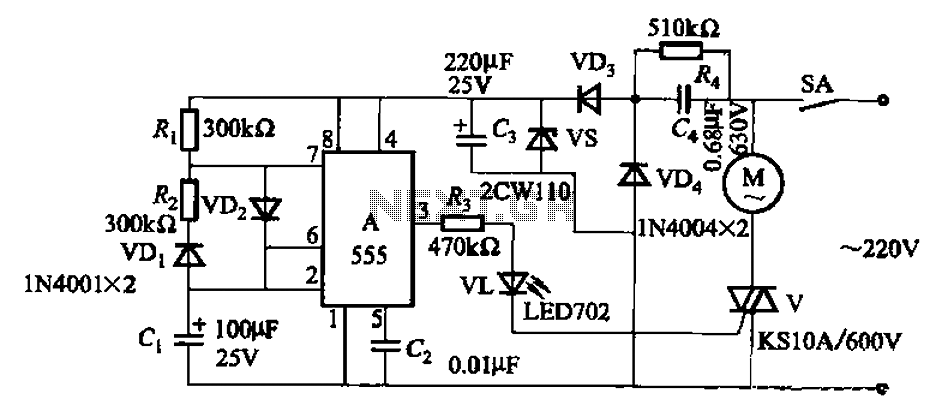
The circuit depicted in Figure 3-16 utilizes a 555 IC (Integrated Circuit) as the control element. It features a capacitive step-down circuit and incorporates a bidirectional thyristor (V) for intermittent motor control operation. By adjusting the resistance values of...
The Johnson 275 watt and Kilowatt Matchboxes are often seen as exaggerated and unfairly criticized. They are neither exceptional tuners nor poorly designed. The main drawbacks include the fixed coupling link and the fact that they are balanced voltage...
A collection of guitar fuzz, preamp, and operational amplifier (op-amp) electronic circuits and schematics designed for various guitar effects and distortion effects. This compilation includes a diverse range of electronic circuits that cater to guitarists seeking to enhance their sound...
A ceramic resonator can be utilized to construct an oscillator. A single digital inverter can be employed to create a Pierce oscillator. To design a Pierce oscillator using a ceramic resonator and a digital inverter, the following components and configurations...
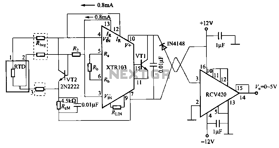
When the RTD temperature sensor is positioned far from the amplifier, the resistance of the sensor leads and their susceptibility to interference and other issues cannot be overlooked. The circuit shown in the figure addresses this problem. It utilizes...
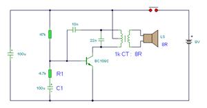
The simple bell circuit without IC. It includes a doorbell circuit that can produce different sounds using integrated circuits, transistors, and resistors. The circuit utilizes a coded trigger mechanism to differentiate between various visitors. When the button is pressed,...