
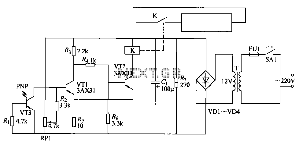
555 Pulsing Third Brake Light Circuit
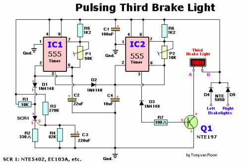
The dual 555 timer circuit operates in astable mode, generating a continuous square wave output. Each 555 timer functions independently but can be synchronized for specific applications. The circuit's frequency and duty cycle are determined by external resistors and capacitors connected to each timer.
In this configuration, the timing components for each 555 timer are typically arranged as follows: two resistors (R1 and R2) and one capacitor (C1) for the first timer, and two resistors (R3 and R4) and another capacitor (C2) for the second timer. The frequency of oscillation (f) can be calculated using the formula:
f = 1.44 / ((R1 + 2R2) * C1)
The duty cycle (D) is given by:
D = (R2 / (R1 + 2R2)) * 100%
The output from the first 555 timer can be used as the trigger input for the second 555 timer, allowing for complex timing sequences or pulse-width modulation applications. The inclusion of the 1N4148 diode may serve to protect the circuit from reverse polarity or to facilitate quick discharge paths for the timing capacitors, enhancing the reliability of the oscillation.
Overall, this dual 555 timer circuit is versatile and can be applied in various electronic projects, including LED flashers, tone generators, and other timing applications. Proper selection of the resistors and capacitors will enable fine-tuning of the output frequency and duty cycle to meet specific design requirements.The Circuit consists of two 555 timer/oscillators in a dual timer configuration both setup in unstable mode. Component: 1N4148 Diode, 555 IC, .. 🔗 External reference
Related Circuits
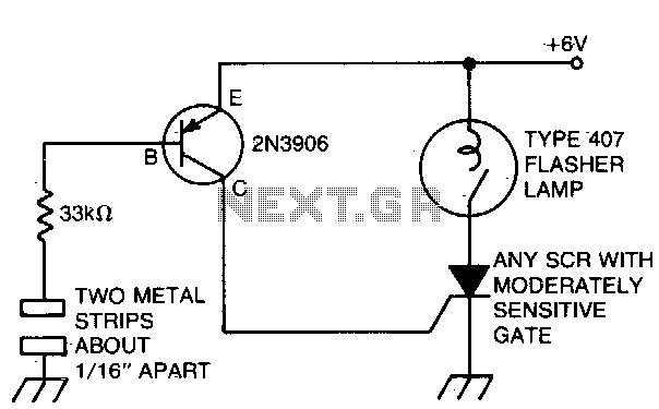
The battery-powered light activates with ease, remaining illuminated for a few seconds before automatically shutting off. The circuit is engaged when a finger bridges the gap between two metal strips, approximately 1/16 inch apart. Sufficient current flows through the...
The high-frequency signal generator is designed to produce a low frequency of 1 kHz, an intermediate frequency (IF) signal of 465 kHz, and high frequencies ranging from 525 kHz to 1605 kHz. This device is particularly useful for radio...
Even including labor, the actual cost of purchasing, stocking, assembly, assembly errors, more expensive PCBs (with additional holes and larger sizes), and the increased difficulty in tuning would likely result in significantly higher expenses. The analysis of costs associated with...
The cutter is safeguarded by a printed circuit phototransistor designed to prevent accidental activation of the cutter switch during manual feeding. In the event of manual feeding, the automatic paper cutter can be controlled to shut down. A relay...
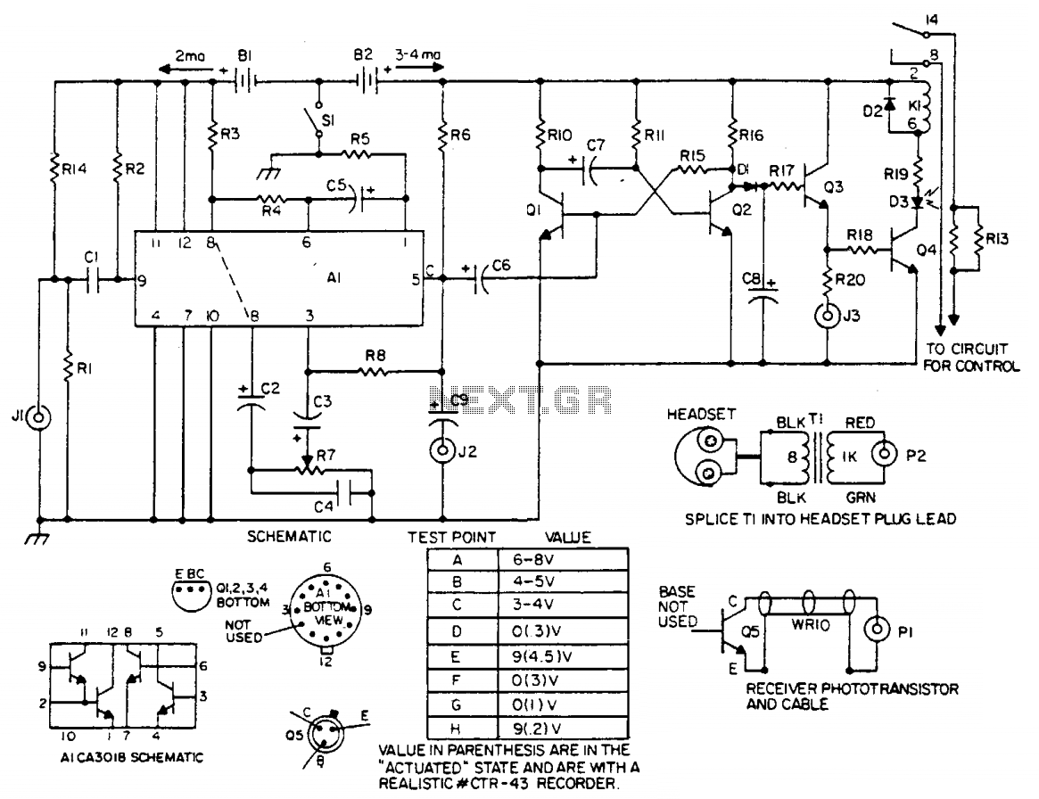
The laser light detector employs a sensitive phototransistor (Q5) positioned at the focal point of a lens (LE2). The output from Q5 is directed to a sensitive amplifier composed of an array (A1), which is biased through a voltage...
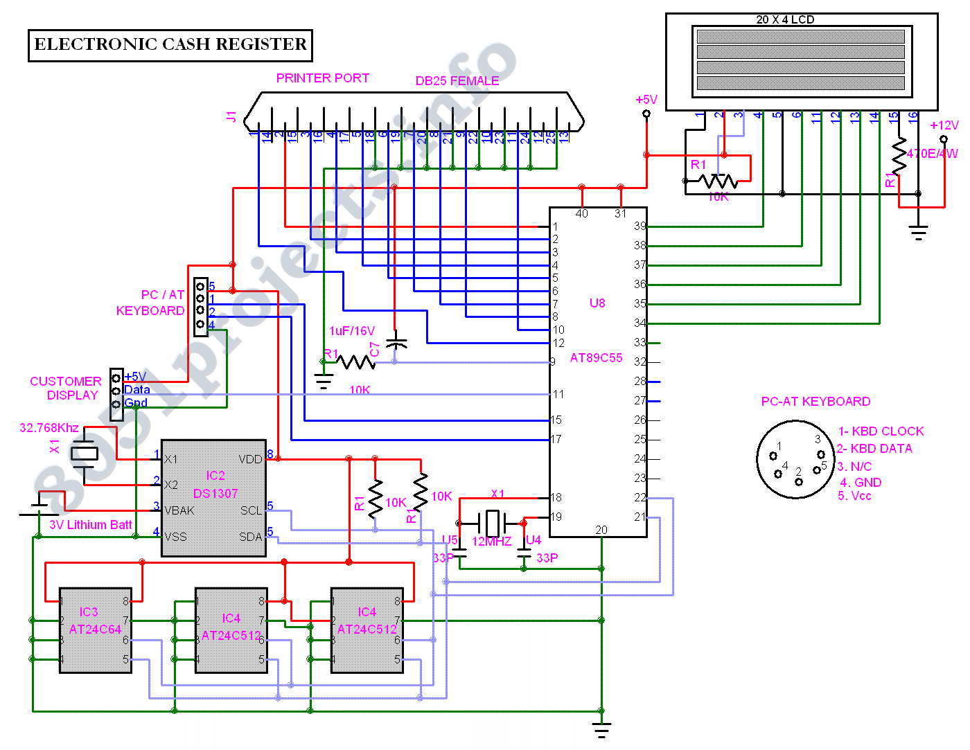
The Electronic Cash Register (ECR) keeps track of sales transactions quickly and effectively. An abundance of PLUs (Price Look Ups) and department keys accommodate a variety of merchandise items. This means a faster, more accurate check out process and...
Warning: include(partials/cookie-banner.php): Failed to open stream: Permission denied in /var/www/html/nextgr/view-circuit.php on line 713
Warning: include(): Failed opening 'partials/cookie-banner.php' for inclusion (include_path='.:/usr/share/php') in /var/www/html/nextgr/view-circuit.php on line 713