
Tin Can Waveguide WiFi Antenna

The Cantenna is a simple yet effective DIY antenna designed to enhance the range of wireless networks, particularly WiFi. The fundamental principle behind this design is based on waveguide technology, where the tin can acts as a waveguide that directs the radio frequency (RF) signals.
To construct a Cantenna, the following materials are typically required:
- A clean, empty tin can (e.g., a soup can or a coffee can)
- A coaxial cable with an appropriate connector for the wireless device (usually an N-type connector)
- A drill or a sharp tool to create an opening in the can
- A ruler or measuring tape
- Optional: paint or tape for aesthetic purposes
The construction process involves the following steps:
1. **Preparation of the Can**: Remove any labels and clean the can thoroughly. It is essential to ensure that the can is free of any contaminants that may affect performance.
2. **Determining Dimensions**: The length of the can and the diameter are critical parameters. For optimal performance, the can's length should be approximately one-quarter of the wavelength of the desired frequency, which for typical WiFi (2.4 GHz) is about 31 mm. The diameter of the can should be around 10 cm to effectively capture the signals.
3. **Creating the Aperture**: Using a drill, create a small hole in the side of the can that is aligned with the center. This hole will accommodate the coaxial cable. The position of the hole should be determined based on the calculated dimensions for the specific frequency being targeted.
4. **Installing the Coaxial Cable**: Insert the coaxial cable through the hole, ensuring that the inner conductor is positioned at the correct depth from the open end of the can. The outer shield should be connected to the can, which acts as a ground.
5. **Final Assembly**: Ensure that all connections are secure and that the can is positioned in a way that maximizes exposure to the intended signal direction.
6. **Testing and Adjustments**: Once assembled, the Cantenna can be connected to the wireless device. It is advisable to test the antenna's performance in various orientations and locations to determine the best setup for maximum signal strength.
The Cantenna is a cost-effective solution for individuals seeking to extend their wireless network coverage without the need for expensive equipment. However, caution is advised regarding the safety and compatibility with existing wireless devices. It is recommended to monitor the performance and ensure that the antenna does not interfere with the device's operation.Got no dough for a commercial WiFi antenna? Looking for an inexpensive way to increase the range of your wireless network? A tin can waveguide antenna, or Cantenna, may be just the ticket. This design can be built for under $5 U.S. and reuses a food, juice, or other tin can. I am not an electrical engineer, nor do I have access to any fancy test equipment. I`ve built some antennas that worked for me and thought I would share what I learned. I have no idea if this is safe for your radio or wireless network equipment. The 🔗 External reference
Related Circuits
Nowadays, a switch-off delay for vehicle interior lighting is a standard feature. However, certain models with minimal settings or older vehicles leave users in the dark as soon as they enter and close the door. This situation calls for...
A frequency reference for tuning up the RS-232 to 100 MHz RF desktop channel adapter elsewhere on this site, when I found this Saronix crystal oscillator in my junk box. A few minutes with AVRStudio produced an ATtiny12 to...
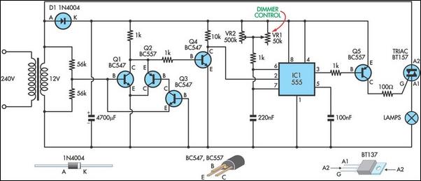
This circuit serves as the foundation for the dimmers in a model theatre lighting system that utilizes touch globes as the light source. The circuit is centered around a 55. This circuit design incorporates a dimmer functionality specifically tailored for...
The following article is a continuation of the application note titled "Defining and Testing Dynamic Parameters in High-Speed ADCs, Part 1." It outlines the test conditions and setup recommendations necessary for effectively measuring the dynamic performance parameters of high-speed...
This schematic illustrates an FM, AM/MW, and SW antenna amplifier circuit, also referred to as an antenna preamplifier circuit. It is designed to enhance weak signals from FM, AM/MW, and SW bands. The circuit is straightforward and can be...
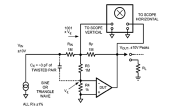
The diagram below illustrates a classic test fixture that has been utilized for an extended period to assist individuals in addressing non-linearity errors. The classic test fixture depicted in the diagram serves as a fundamental tool in electronics testing and...