
Vehicle Interior Lighting With Switch-Off Delay
The described circuit serves as an effective solution for vehicles lacking an integrated delay feature for interior lighting. The design utilizes a Darlington transistor configuration, which is known for its high current gain, making it suitable for controlling the interior light with minimal input current. The use of a heatsink for the power transistor T3 is critical, as it dissipates heat generated during operation, ensuring the transistor operates within safe thermal limits.
The circuit board layout is optimized for SMD assembly, which helps in reducing the overall footprint and enhancing reliability. The four mounting holes provide robust mechanical support, ensuring that the assembly remains securely attached to the heatsink, which also serves as a common ground reference.
The operation sequence begins when the vehicle door is opened, triggering the circuit to power the interior light. The initial bright illumination for 30 seconds allows for visibility when entering the vehicle. Following this, the gradual dimming of the light creates a softer ambiance, preventing abrupt darkness and enhancing user comfort.
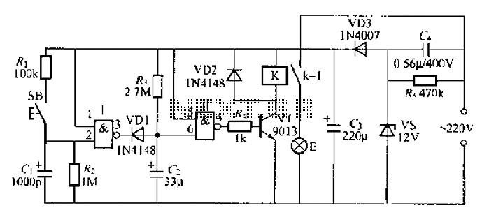
The design's quiescent current dropping to zero after one minute signifies that the circuit is energy-efficient, as it prevents battery drain when the vehicle is not in use. This feature is particularly beneficial for older vehicles that may not have modern power management systems. The circuit is suitable for aftermarket installation, providing a valuable enhancement to the vehicle's existing electrical system.Nowadays, a switch-off delay for the vehicle interior lighting is a naturally a standard feature. However, with certain models having only spartanttings, or older-model vehicles, you`re left sitting in the dark as soon as you climb in and close the door. That calls for an aftermarket accessory! The author built this circuit using normal` compo nents (with leads), but in the SMD manner, which meanstting the components on the copper side. The only holes drilled in the circuit board were the fourxing holes, and the entire assembly wasrmly attached to the surface of the heatsink for power transistor T3 (the author used a finned heat sink rated at 7. 2 °C/W). The heatsink is at ground potential. A value of 1 was used for R3 with satisfactory operation of the darlington. The light goes on when the door is opened. After the door is closed, it continues to illuminate the interior of the car at full brightness for around 30 seconds, after which it slowly dims.
Approximately 1 minute after the door is closed, the quiescent current drops to zero. 🔗 External reference
Related Circuits
Described timer to participate in the current circuit switch - bulb without any modification of existing pipelines. Connect the timer is in Figure 1 The time switch has only two outlets, which is connected in parallel to the button...
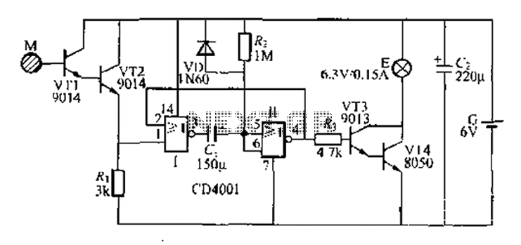
A two-battery powered light touch delay circuit designed for convenience at night. It can be placed on a bed pillow, and when the metal contact M under the capsule is touched, a small lamp will automatically light up. The...
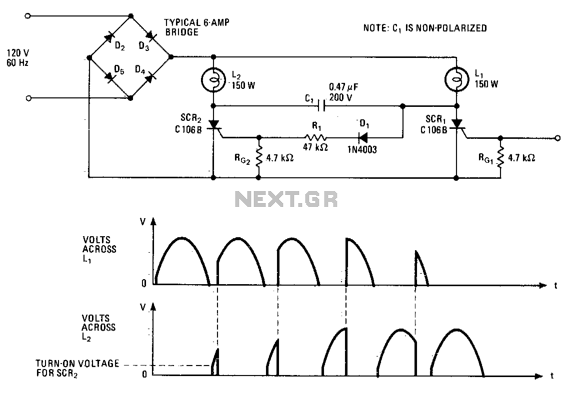
This lighting control unit will gradually decrease the brightness of one lamp while simultaneously increasing the brightness of another. The two loads maintain precise tracking without the need for manual adjustments. The gate of SCR1, a silicon-controlled rectifier, is...

A 3D enhancement is required to achieve a fully three-dimensional sound experience for most stereo multimedia products. Typically, simple phase-delay circuits are utilized to create a widening effect on the perceived sound field. However, this approach can lead to...
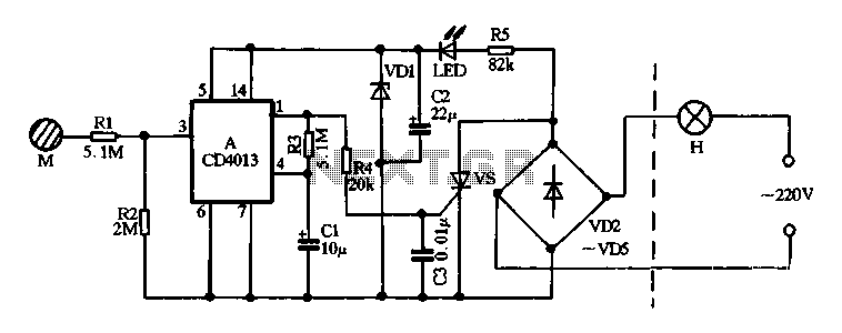
Diodes VD2 to VD5 and SCR form the main circuit of a touch switch. Resistor R5 and diode VD1 create a power supply circuit that outputs approximately 12V DC, which is utilized for a manifold A application. The circuit...
A 2-input NAND gate integrated circuit is used in the fabrication of a digital delay lamp circuit. This circuit is energized by a simple capacitive voltage rectifier, which operates by crossing the half line. The output terminal indicates the...
Warning: include(partials/cookie-banner.php): Failed to open stream: Permission denied in /var/www/html/nextgr/view-circuit.php on line 713
Warning: include(): Failed opening 'partials/cookie-banner.php' for inclusion (include_path='.:/usr/share/php') in /var/www/html/nextgr/view-circuit.php on line 713