
DC motor controller diagram with SCR and cmos ic
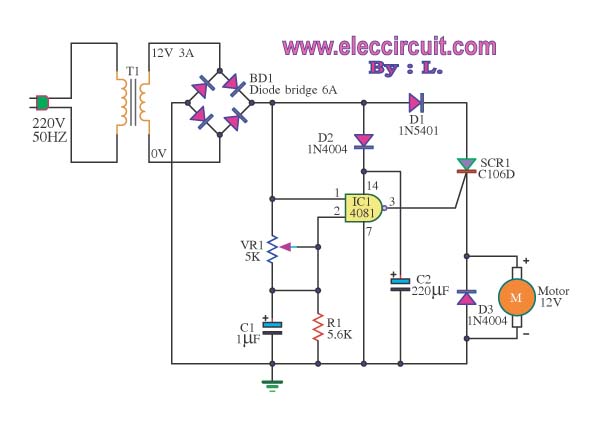
The speed motor controller circuit for a 12V DC motor typically includes several key components that work together to regulate the motor's speed. The circuit may consist of a variable resistor (potentiometer), a transistor or MOSFET for switching, a diode for flyback protection, and a microcontroller or timer IC for precise control.
The potentiometer allows the user to set the desired speed by varying the resistance in the circuit, which in turn adjusts the voltage supplied to the motor. The transistor or MOSFET acts as a switch that controls the power delivered to the motor based on the input from the potentiometer. This switching action can be implemented using Pulse Width Modulation (PWM) to efficiently control the speed without wasting energy.
The diode placed in parallel with the motor serves as a flyback diode, protecting the circuit from voltage spikes generated when the motor is turned off. This is crucial for maintaining the longevity and reliability of the components.
For precise speed control, a microcontroller or timer IC can be integrated into the circuit. This allows for more advanced features such as speed feedback, acceleration profiles, and the ability to set maximum speed limits. The output from the microcontroller can modulate the duty cycle of the PWM signal, providing a smooth and responsive control over the motor's speed.
Overall, this speed motor controller circuit is designed to provide efficient and adjustable control over the operation of a 12V DC motor, making it suitable for various applications where precise speed regulation is necessary.This is speed motor controller circuit of 12V DC motor. You can adjust the speed of rotation of the spindle motor from 5-60 cycles per minute. The work of.. 🔗 External reference
Related Circuits
Stepper motors are a recurring subject. This circuit converts a clock signal from a square wave generator into signals with a 90-degree phase shift. Stepper motors are widely used in applications requiring precise control of angular position, speed, and acceleration....
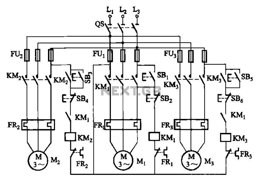
The circuit shown in Figure 3-89 illustrates a system where starting motor M1 allows motors M2 and M3 to initiate operation. Upon shutdown, motor Mz can be stopped first; however, once motor M1 is stopped (by pressing switch SB2),...
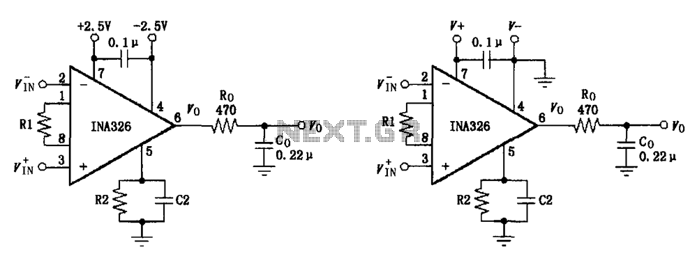
The basic connection circuit for the INA326/327 includes signals and power. A 0.1 µF capacitor is selected for power supply filtering and should be placed as close to the chip's supply pin as possible. Ro and Co serve as...
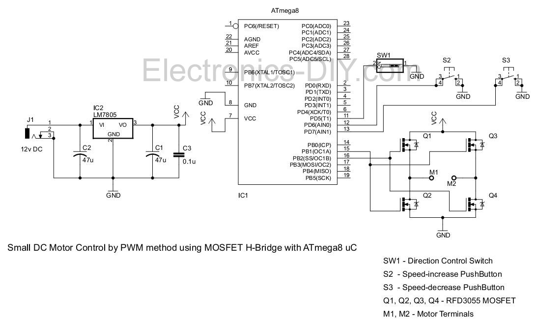
This project involves controlling a small DC motor, sourced from an old personal cassette player, using the ATmega8 microcontroller. The ATmega8 features three PWM channels, of which two are utilized in this application. The PWM signals are sent to...
Instructions for supervising landscaping projects recommended by satellite relay protection and automatic safety devices. This includes information on the general table for three remote programs related to petrochemical engineering construction, electrical transmission, and the intelligent implementation of community weak...
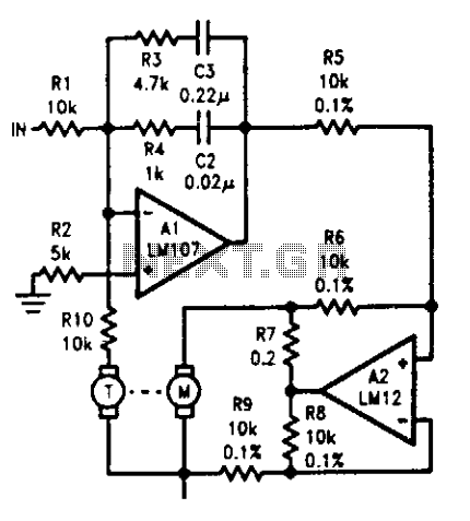
The tachometer, mounted on the same shaft as the DC motor, functions as a generator, producing a DC output voltage that is proportional to the motor's speed. A summing amplifier, labeled as Al, manages its output to ensure that...