
Digital to analog converter using R 2R ladder network and 741 op amp with simulated output waveform
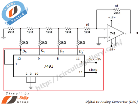
The Digital to Analog Converter (DAC) operates by converting discrete digital signals into continuous analog voltages. The R-2R ladder network is a preferred architecture due to its simplicity and cost-effectiveness. The network consists of resistors arranged in a specific manner, where each bit in the binary input corresponds to a resistor value. The resistors are configured such that each successive bit has a value that is double the previous bit, thereby creating a binary-weighted system.
In the R-2R ladder, the resistors R and 2R are alternately arranged, allowing for straightforward scaling of the voltage levels based on the binary input. For example, if the least significant bit (LSB) is active (high), it contributes a voltage level of Vref/2, while the next bit contributes Vref/4, and so on. This structure allows the DAC to produce an output voltage that is a precise representation of the binary input.
The summing amplifier, typically implemented using an operational amplifier like the 741, plays a crucial role in this configuration. It sums the voltages produced by the R-2R ladder network and amplifies the result based on the feedback and input resistor values (Rf and Ri). The gain of the summing amplifier can be adjusted to achieve the desired output voltage range.
The 7493 counter IC, while not part of the DAC itself, provides the necessary digital inputs to the R-2R network. By applying various combinations of binary inputs (D3, D2, D1, D0), the counter can generate a sequence of digital values that the DAC converts into corresponding analog voltages. This feature allows for versatility in applications where varying analog signals are required from digital sources.
In summary, the R-2R ladder network DAC is an efficient solution for converting digital signals into analog voltages, leveraging the simplicity of resistor networks and the amplification capabilities of operational amplifiers. Proper attention to resistor selection and circuit configuration is essential for achieving high precision and performance in DAC applications.What is DAC Digital to analog converter (DAC) is used to get analog voltage corresponding to an input digital data. Data in binary digital form can be converted to corresponding analog form by using a R-2R ladder (binary weighted resistor) network and a summing amplifier.
It is more common and practical. Below is the circuit and output simulated waveform of R-2R ladder network DAC. This circuit also uses an op amp (741) summing amplifier circuit. You can learn how to build a Digital to Analog converter using the simple technique explained in this page. Actually different types of Digital to Analog converter ICs are available commercially based on this same principle.
The R-2R ladder network is build by a set of resistors of two values. It makes the circuit more simple and economical for different applications. R-2R weighted resistor ladder network uses only 2 set of resistors- R and 2R. If you want to build a very precise DAC, be precise while choosing the values of resistors that will exactly match the R-2R ratio. For 0001 onlyD0=Vref, all other inputs are at 0V and can be treated as ground. So finallyVref/16volt is appearing as the input to op amp. This value gets multiplied by the gain of op amp circuit (Rf/Ri). In this circuit the 7493 IC simply provides digital inputs to DAC. It is a counter IC and not an integral part of the DAC circuit. You can apply any combinations of binary inputs toD3D2D1D0 🔗 External reference
Related Circuits
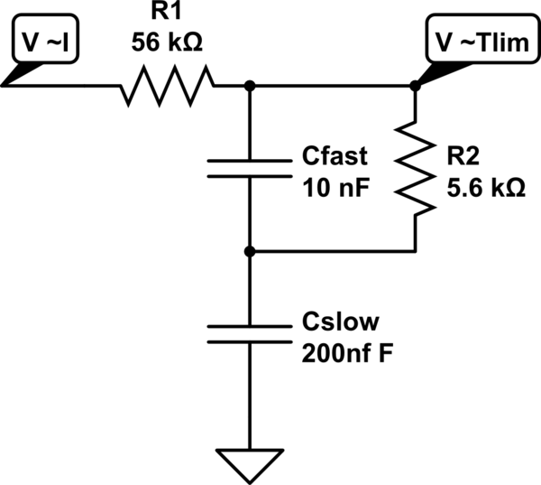
A MOSFET is employed to drive a load that includes a sense resistor in its current path. The voltage across this resistor is utilized to trigger a circuit capable of disconnecting the load in the event of an overcurrent...

In recent years, there has been a growing demand for higher reimbursement structures among music lovers and manufacturers of tube amplifiers. This is attributed to the perception that tube sound is sweeter, richer, and incomparably cleaner. However, tube amplifiers...
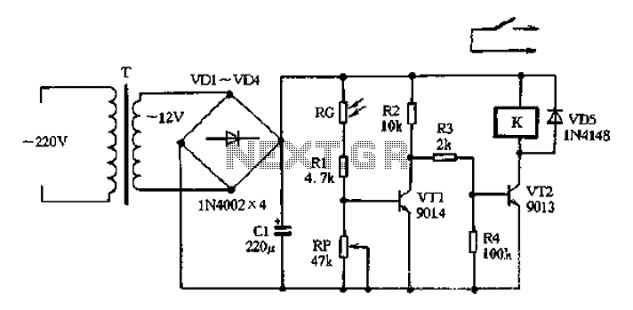
The circuit operates on 220V AC input, which is transformed to approximately 12V DC using a step-down transformer (T), a diode bridge rectifier (VDI-VD4), and a filter capacitor (C1). This setup is designed to power the entire circuit. The...
The project involves constructing two similar EMG circuits with different gain settings to measure electromyography (EMG) signals from two forearm muscles: the Flexor Digitorum Superficialis (FDS) and the Extensor Carpi Radialis Longus (ECRL). The outputs from these circuits will...
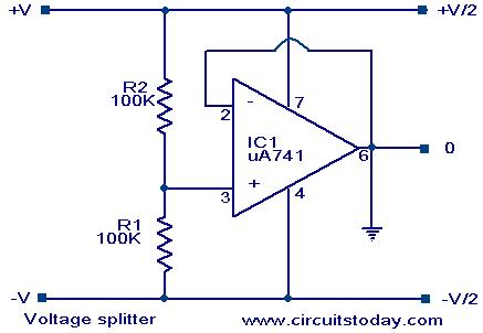
Voltage splitter using op-amp uA741 IC, circuit diagram, working, description. The voltage splitter circuit utilizing the uA741 operational amplifier (op-amp) is designed to provide a stable output voltage that is a fraction of the input voltage. The uA741 is a...
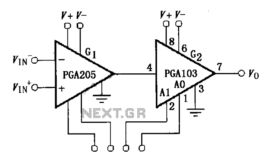
The circuit depicted in the figure comprises a PGA103 programmable gain instrumentation amplifier. This design utilizes the PGA205 and PGA103 in a cascading configuration, resulting in a total gain for the amplifier. The gain is determined by the product...
Warning: include(partials/cookie-banner.php): Failed to open stream: Permission denied in /var/www/html/nextgr/view-circuit.php on line 713
Warning: include(): Failed opening 'partials/cookie-banner.php' for inclusion (include_path='.:/usr/share/php') in /var/www/html/nextgr/view-circuit.php on line 713