
A non-contact automatic flashing lights circuit
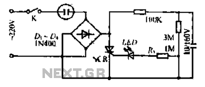
The described circuit is a 20V power supply designed for a child-friendly application, particularly for illuminating a decorative light associated with foreign vine wine themes. The circuit employs a bridge rectifier to convert alternating current (AC) to direct current (DC), ensuring a stable power supply for the lamp. The inclusion of a triac allows for effective control of the current flow to the lamp, enabling dimming and flashing effects.
The circuit's architecture consists of several key components: a series of resistors (R), capacitors (C1, C2), and a silicon-controlled rectifier (SCR). The resistors are utilized to limit current and set voltage levels throughout the circuit, while the capacitors serve to smooth out fluctuations in the output voltage, providing a more stable operation.
The SCR plays a crucial role in the operation of the lamp. When the gate of the SCR is triggered by the discharge from C2, the SCR turns on, allowing current to flow through the lamp and illuminate it. The design ensures that the SCR remains on until the current drops to zero, at which point it turns off, creating a flashing effect. This zero-crossing feature is significant as it minimizes electrical noise and potential flickering in the lamp.
The flashing interval of the lamp can be adjusted by modifying the values of the resistors and capacitors in the circuit. This flexibility allows for customization of the flashing pattern, enhancing the aesthetic appeal of the light. Overall, this circuit is suitable for decorative applications where a child-friendly design is paramount, combining functionality with visual charm.20V child fS/iff power over a foreign vine wine Kiiit, bulb and plug Mount the bridge rectifier circuit. Poke seat access lamp LL n © number ur using 10- IOOW front with a smal l size. Kui stream output lm termination triac Sci m by releasing member .! Touch redundant circuit Torr, R, R, Cl C2 composed towel in c people capacity rectifier output voltage through R j Sh [ : charging, when the island Jl: cockroach end electric charge to set a plan when, CzMdR: iuJSCR gate discharge, SCR is turned on, the lamp is lit J sac. Organisation current voltage zero crossing. SCR blocking the light is off, the island charge again i had called the process repeated setbacks lights flashing light.
Sheet sparkle spider interval time can be had by coups and foot bundle adjustment.
Related Circuits
The bearing fault detector circuit consists of a bearing detection sensor, a signal processing circuit, a transistor (V), an audio amplifier integrated circuit (IC2), a speaker (BL), an RC element, an integrated circuit (IC1), and a light-emitting diode (VL)....
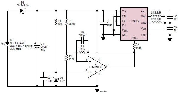
A simple supercapacitor charger electronic project can be designed using the LTC3625 integrated circuit (IC) from Linear Technology. This circuit is capable of charging two supercapacitors in series to a fixed output voltage of either 4.8V/5.3V or 4V/4.5V, which...
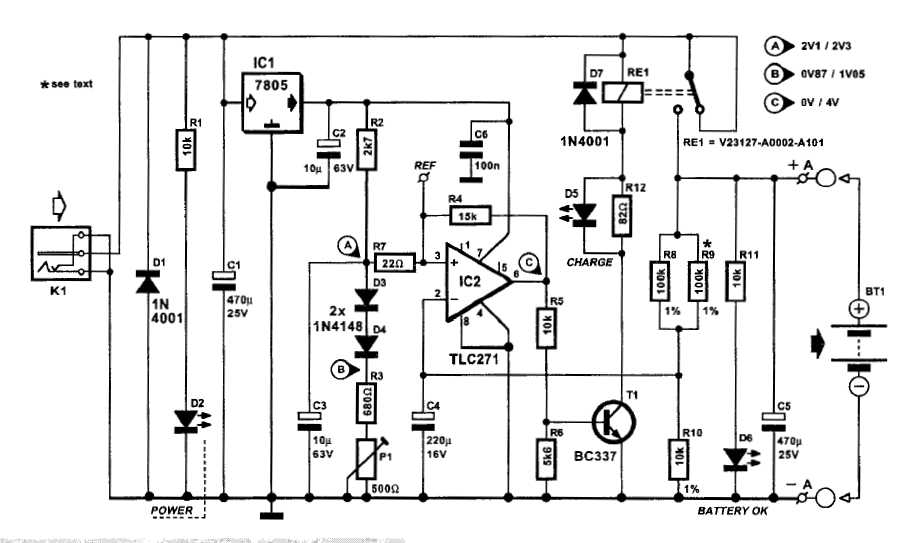
An automatic battery charger initiates the charging process when the battery voltage falls below a specified threshold and ceases charging once the voltage exceeds a predetermined maximum value. The setup is straightforward; simply connect two alligator clips to the...
An RF probe is a circuit designed for testing equipment that converts high-frequency signals into DC voltage. This conversion facilitates the measurement of RF voltages for testing or adjusting transmitters, receivers, and modulators. The RF probe circuit outlined here...

The TDA2030 amplifier circuit is suitable for driving low-frequency subwoofer speakers in home theater systems. The TDA2030 is a monolithic integrated circuit designed for use as a low-frequency class AB amplifier. This TDA2030 amplifier design requires a dual power...
A basic digital voltmeter circuit utilizing the Harris Semiconductor ICL7107 is presented. It operates within a 2-V range. Calibration involves applying a known voltage of 1.2 V to the input and adjusting resistor R3 to achieve an accurate reading...