
Toaster Oven Reflow Technique
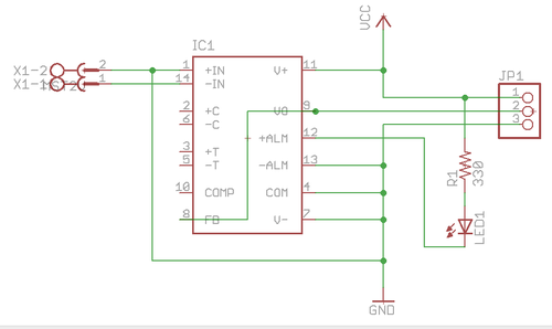
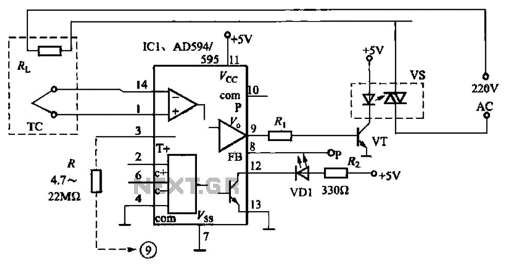
Any toaster oven can be utilized, provided its power rating is not excessively high. A solid-state relay, capable of switching 5A, is recommended (power = volts x amps). The solid-state relay can be sourced from Farnell, along with a K-type thermocouple and thermocouple amplifier. Alternatively, thermistors similar to those used in RepRap extruders can serve as temperature sensors, as they operate within a similar temperature range. If the firmware reports incorrect temperatures or the warning LED activates, it is likely that the thermocouple wires are reversed and should be swapped.
For optimal use, the solid-state relay can be mounted inside a mains plug patress box, transforming it into a versatile device to control any mains load (up to 5A) using an Arduino. Control wires should exit the side of the box and connect to the Arduino: the positive wire connects to the Arduino LED (D13 on an Arduino Diecimila), while the other control wire connects to the Arduino ground. It is important to note that there is no electrical connection between the control circuit and the mains circuit within the solid-state relay, as it is optically coupled, ensuring safety from mains voltage reaching the Arduino, provided the wiring is correct.
The relay's switched side should be connected in series with the live wire of the cable leading to the socket's live terminal, while the neutral and earth wires should be connected directly to their respective socket terminals. All exposed live connections must be insulated thoroughly with heat-shrink tubing. Two wires should be run from the control pins to the Arduino as previously described, and color coding is recommended to easily identify the positive wire when reassembling the electric socket.
The timing is not overly critical, but it is essential to avoid prolonged exposure of the components to high temperatures. The maximum temperature is set to 215°C, although it may overshoot slightly to 220°C, which is the desired temperature.
The provided code snippet controls the heating process. The `heatPin` variable corresponds to the pin used for the heater, while `heatState` indicates the heater's current state. The `long previousMillis` and `const long interval` variables manage the timing of temperature sampling. The `tempPin` variable is assigned to the analog pin used for temperature measurements. The temperature profile is defined in a two-dimensional array, with each entry representing a time-temperature pair. The `target` function linearly interpolates the desired temperature based on the elapsed time. The `temperature` function reads the actual temperature from the thermocouple.
The `setup` function initializes the necessary pin modes and starts serial communication for monitoring. The `loop` function continuously checks and updates the heating process, ensuring that the soldering operation is executed efficiently and safely.This page describes how to reflow solder surface mount printed circuits using a cheap toaster oven. It owes a great deal to Nophead`s Cooking with Hydraraptor blog post. The picture shows Sally Bowyer (Director, RepRapPro Ltd ) preparing components for soldering in the oven. For more instructions on this see the video at the bottom of this page. Just about any toaster oven will do, as long as its power rating is not too high. The solid-state relay (see below) can switch 5A; power = volts x amps; do the mathematics. We use this solid-state relay from Farnell, and a K-type thermocouple plus thermocouple amplifier (see below). Alternatively you could use the same types of thermistors that RepRap uses for its extruders as temperature sensors - the temperatures are about the same.
If you get silly temperatures reported by the firmware (see below) or the warning LED lights, then the thermocouple wires are the wrong way round. Swap them. The neatest thing to do with the solid-state relay is to mount it inside a mains plug patress box. You will then have a general-purpose device that will allow you to control any mains load (up to 5A) with the Arduino.
Run the control wires out of the side of the box and connect them to the Arduino: + goes to the Arduino LED (D13 on an Arduino Diecimila), the other control connection goes to the Arduino ground. Note that there is no electrical connection inside the solid-state relay between the control circuit and the mains circuit.
The device is optically coupled, so there is no danger that you will get mains flowing through your Arduino (as long as you wire things up right. ). Put the relay`s switched side in series with the cable`s live wire on the way to the live terminal of the socket; run the neutral and earth straight through to their socket terminals.
Insulate any exposed live connections carefully with heat-shrink. Run two wires from the control pins to the Arduino as described above. Colour code them so you can remember which one is + when the electric socket is put back together. The timings are not too critical, but you don`t want the components to stay at the highest temperature for too long. The highest temperature is set to 215oC, but you will find that this overshoots a bit to 220oC, which is the actual temperature you want.
/* Toaster Oven SMT soldering control Adrian Bowyer 2 November 2011 Licence: GPL */ const int heatPin = 13; // the number of the LED pin. This also controls the heater int heatState = LOW; // heatState used to set the LED and heater long previousMillis = 0; // will store last time LED/heater was updated const long interval = 1000; // interval at which to sample temperature (milliseconds) const int tempPin = 0; // Analogue pin for temperature reading long time = 0; // Time since start in seconds bool done=false; // Flag to indicate that the process has finished // The temperature/time profile as {secs, temp} // This profile is linearly interpolated to get the required temperature at any time.
// PLEN is the number of entries #define PLEN 6 long profile[PLEN][2] = { {0, 15}, {120, 150}, {220, 183}, {280, 215}, {320, 183}, {350, 0} }; // Linearly interpolate the profile for the current time in secs, t int target(long t) { if(t <= profile[0][0]) return profile[0][1]; if(t >= profile[PLEN-1][0]) { done = true; // We are off the end of the time curve return profile[PLEN-1][1]; } for(int i = 1; i < PLEN-1; i+) { if(t <= profile[i][0]) return (int)(profile[i-1][1] + (t - profile[i-1][0])*(profile[i][1] - profile[i-1][1])/ (profile[i][0] - profile[i-1][0]); } return 0; } // Measure the actual temperature from the thermocouple int temperature() { return ( 5. 0 * analogRead(tempPin) * 100. 0) / 1024. 0; } // Get the show on the road void setup() { pinMode(heatPin, OUTPUT); pinMode(tempPin, INPUT); Serial.
begin(9600); Serial. println(" Time, target, temp"); done = false; } // Go round and round void loop() { int 🔗 External reference
Related Circuits
Introduction to the Reflow Process and PID Controller Circuit Documentation. This document discusses the benefits of using Surface Mount Devices (SMD) in circuit design, highlighting advantages such as reduced size and cost compared to traditional through-hole components. The reflow soldering...
This circuit is designed to charge NiCd or NiMH batteries using solar cells. It maximizes power extraction from a solar array to charge a battery stack. The circuit utilizes the MAX856 boost converter and the MAX982 dual comparator with...
An automatic electric furnace temperature controller is depicted in FIG. 1-25. The closed circuit is established through a temperature detection output control loop. As the temperature rises, the output voltage increases. When the voltage reaches a preset temperature value,...
The SK1901 is a semiconductor integrated circuit that employs the Hall effect. It is specifically designed to function in alternating magnetic fields, particularly at low supply voltages and across a wide temperature range, up to +125°C. This Hall integrated...
The OPB350 series liquid sensor is designed to operate with clear tubes of various outer diameters: 1/16 inch (1.6 mm), 1/8 inch (3.2 mm), 3/16 inch (4.8 mm), and 1/4 inch (6.3 mm). When integrated with output reference circuitry,...
Capacitive sensors are utilized in various devices, ranging from consumer electronics to industrial and process control systems. Touch buttons are increasingly integrated into lamps and dimmers, while motion detectors can sense minute changes in deflection. Hygrometers measure humidity levels,...