
Solid State Power Controllers

The circuit design incorporates two 555 timer ICs, which are versatile components widely used in various timing, pulse generation, and oscillator applications. The first IC (U1) operates as a variable duty cycle oscillator, allowing for dynamic adjustment of the output signal's duty cycle, which is essential for controlling the power delivered to the load. The duty cycle variation is achieved using a potentiometer (R4), providing user-friendly control over the output power.
The second IC (U2) is configured as a Schmitt trigger, which is advantageous for its noise immunity and ability to provide clean, stable output transitions. The hysteresis in the Schmitt trigger ensures that the output state does not oscillate near the threshold voltage, providing reliable switching behavior.
The transformer (T1) and rectifying diodes (D1 and D2) convert the AC input voltage into a unidirectional form suitable for the control circuitry. The filtering capacitor (C1) smooths out the rectified voltage, ensuring stable operation of the Schmitt trigger. The use of a diode (D3) to prevent filtering across R1 is a critical design choice that maintains the input voltage levels necessary for accurate Schmitt trigger operation.
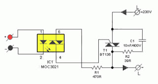
The triac serves as a power switching device, allowing for efficient control of high-power loads. The design allows for zero-crossing switching, which minimizes electromagnetic interference and reduces stress on the load by turning the triac on and off at the zero voltage crossing points of the AC waveform.
The assembly on a general-purpose IC strip board facilitates ease of construction and prototyping, while the linear potentiometer with a plastic shaft provides a user-friendly interface for power adjustment. Safety considerations, such as ensuring the heat sink does not contact a metallic enclosure, are essential for reliable and safe operation of the circuit. Overall, this circuit exemplifies a practical and efficient approach to controlling AC loads with variable duty cycle switching.The circuit is built around two 555 timer ICs. U1 and U2. U1 is wired as a variable duty cycle oscillator with a constant time period of around 0. 1 second. Duty cycle can be varied from 0 to 100 per cent by R4 potentiometer. The output of U1 (pin 3) is connected to the rest input (pin 4) of U2. U2 is wired as a comparator with hystereis, i. e a Schmitt trigger. Diode D6 brings the potential at control voltage (pin 5) terminal at 0. 7V. The threshold (pin 6) and trigger (pin 2) terminals connected together constitute the input. The output (pin 3) of the Schmitt trigger goes high when Vin equals or below 0. 35V and goes low when it is equals or above 0. 7V. Transformer T1 with rectifying diodes D1 and D2 delivers unidirectional AC voltage across R1 with a peak voltage of 8. 5V and 100Hz frequency. C1 is the filtering capacitor. D3 prevents the voltage across R1 from being filtered. Since the input of the Schmitt trigger is connected across R1, its out put will be high when input voltage falls below 0.
35V and remains so till it exceeds 0. 7V. If pin 4 of U2 is left unconnected, the triac will be fired at the start of each half cycle of AC by a short pulse. Hence full power will be delivered to the load. But since output of U1 is connected to the rest input of U2, the Schmitt trigger delivers pulses to the gate of triac only when output of U1 is high.
This explains how variable duty cycle zero crossover switching is accomplished. I have used a 5-amp triac, which is capable of switching loads up to 1000W. Using a triac with larger current rating can also control higher loads. Of course, size of the heat sink will have to be suitably increased. You can build this circuit in a general purpose IC strip board. Potentiometer R4 should be linear with a plastic shaft. It can be mounted on the front portion of the enclosure, with a dial marked from 0 to 100 per cent power at, say 5 per cent intervals. If a metallic enclosure is used, care must be taken to ensure that the heat sink of triac does not touch it anywhere.
🔗 External reference
Related Circuits
The thermostat circuit is designed to control a 1300-watt space heater using a small pulse transformer. Component: LM339 IC. The thermostat circuit utilizes an LM339 integrated circuit (IC) to manage the operation of a 1300-watt space heater. The LM339 is...
The primary advantage of a solid-state relay (SSR) over a traditional electromagnetic relay (EMR) is its reduced wear and tear, which enhances its longevity. The S201S01 model from Clear-Cut serves as an exemplary representation of this technology. The following...
This circuit is essentially a crystal radio equipped with an audio amplifier that demonstrates considerable sensitivity, successfully receiving multiple strong stations in the Los Angeles area using a minimal 15-foot antenna. Employing a longer antenna can enhance signal strength;...
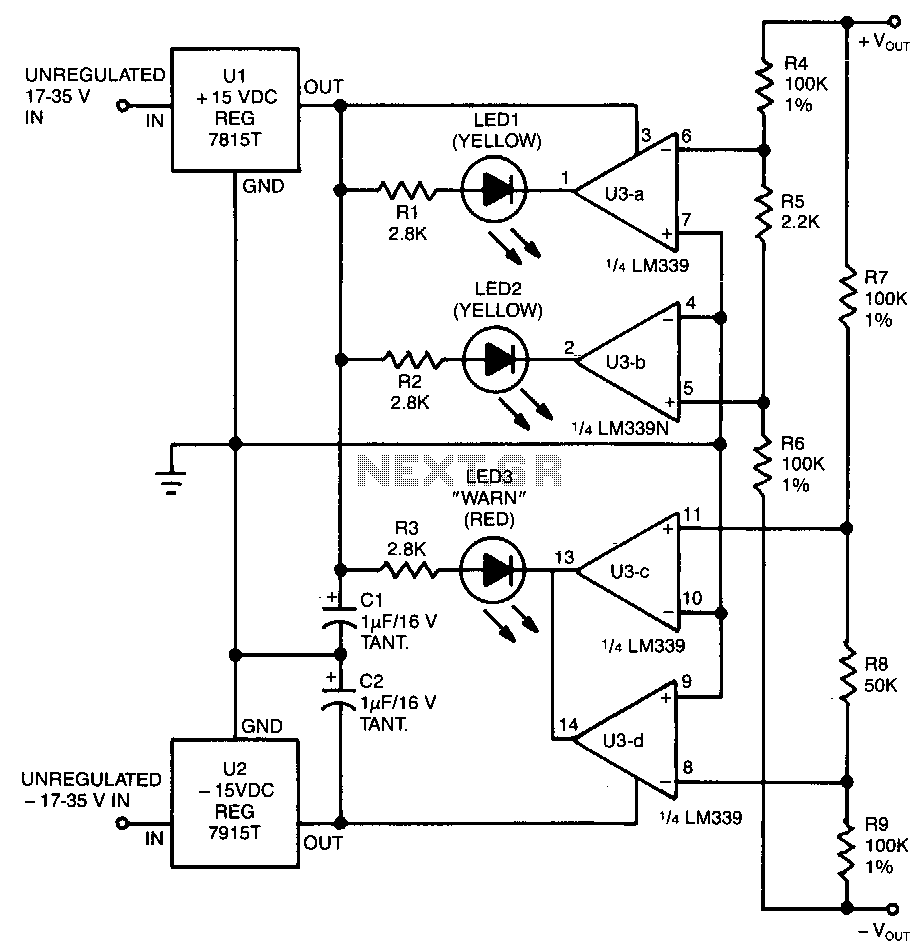
This circuit utilizes two pairs of comparators from an LM339N quad comparator. One pair controls the yellow positive (+) and negative (-) indicators, while the other pair drives the red warning LED3. The circuit is powered by the unregulated...
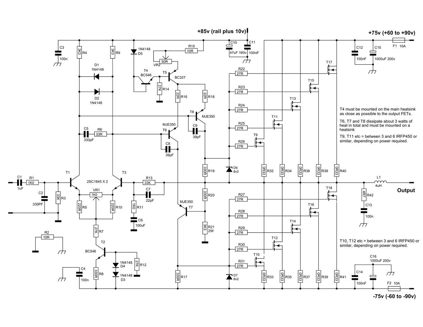
This circuit is a Power Amplifier designed to deliver an output power exceeding 600 Watts for speakers with an impedance of 4 Ohms. The high-power amplifier circuit utilizes six n-channel MOSFETs in the output stage, which alone provides approximately...
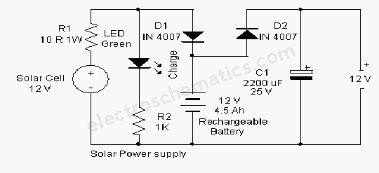
A solar-powered flasher designed to deter nocturnal animals such as bats and cats from agricultural areas or residential premises. The device emits brilliant multicolored flashes that confuse these animals, encouraging them to avoid the area. It operates automatically, activating...
Warning: include(partials/cookie-banner.php): Failed to open stream: Permission denied in /var/www/html/nextgr/view-circuit.php on line 713
Warning: include(): Failed opening 'partials/cookie-banner.php' for inclusion (include_path='.:/usr/share/php') in /var/www/html/nextgr/view-circuit.php on line 713