
Water level alarm circuit using 555 timer

The water level alarm circuit utilizing a 555 timer IC is designed to monitor the water level in a tank and activate an alarm when the water reaches a specified threshold. The circuit operates in a monostable mode, where the 555 timer generates a pulse when triggered by the water level sensor.
The primary components of this circuit include the 555 timer IC, resistors, capacitors, and a water level sensor, which can be a pair of conductive probes or a float switch. The probes are placed at the desired water level, and when water bridges the probes, it triggers the 555 timer.
In the monostable configuration, the timer is triggered by a low voltage signal from the water sensor. Upon activation, the 555 timer outputs a high signal for a predetermined duration, which is set by the resistor and capacitor connected to it. This output can be used to drive a buzzer or an LED indicator to alert users of the high water level condition.
The circuit requires careful calibration of the resistor and capacitor values to ensure that the alarm duration is appropriate for the application. Additionally, the power supply for the circuit should be stable to prevent false triggering.
Overall, this simple water level alarm circuit is an effective solution for monitoring water levels in various applications, such as aquariums, tanks, and reservoirs, providing an audible or visual alert when water levels become critical.This is a simple Water level alarm circuits made using 555 Timer IC. Circuit will produce an alarm when the water level reaches a preset level.. 🔗 External reference
Related Circuits
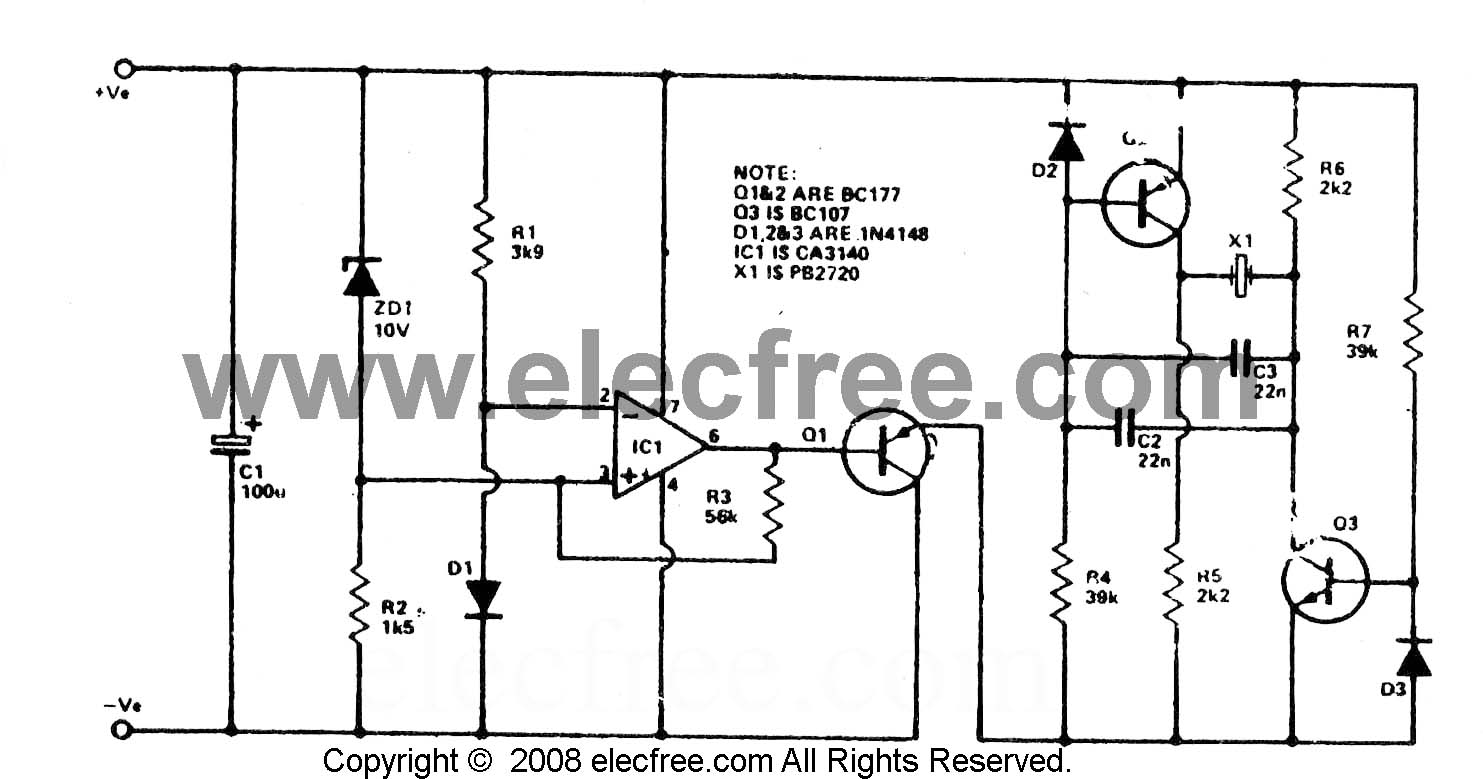
To check the battery in a car, an easy circuit utilizing the IC CA3140 and a transistor is employed. The voltage level of an automobile battery is influenced by many factors, and if it is high... The circuit for checking...
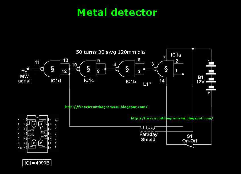
This circuit needs a Faraday shield, which is connected to 0V. To make this one wrap a tin foil around the coil and connect to 0V. Then you can use this circuit to find metal. Tune your mw radio...
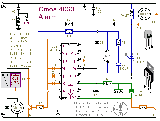
This is a single-zone alarm system equipped with automatic exit, entry, and siren cut-off timers. It is designed to accommodate various types of normally-closed input devices, including magnetic reed contacts, foil tape, and passive infrared sensors (PIRs). Additionally, it...
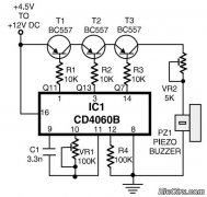
This is a simple home telephone ringtone generator circuit constructed using only a few electronic components. It generates a simulated telephone ringtone and requires a DC supply voltage ranging from 4.5V to 12V. This circuit can be used in...
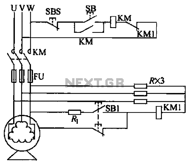
A voltage leakage protection circuit utilizing a resistive element as an auxiliary neutral point is illustrated in the accompanying figure. When selecting the resistance, it is essential to consider both the resistance value and power consistency. The described voltage leakage...
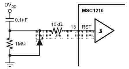
According to the MSC1210 datasheet, you will perform an external reset by taking RST pin high for two tOSC periods as this stops device operation, crystal oscillation, causes all digital pins to be pulled high from that point and...
Warning: include(partials/cookie-banner.php): Failed to open stream: Permission denied in /var/www/html/nextgr/view-circuit.php on line 713
Warning: include(): Failed opening 'partials/cookie-banner.php' for inclusion (include_path='.:/usr/share/php') in /var/www/html/nextgr/view-circuit.php on line 713