
Tone ControlCircuit
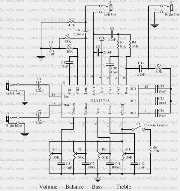
The circuit design incorporates a logarithmic potentiometer (P1) for volume control, allowing for a more natural adjustment of audio levels, particularly important in audio applications. The linear potentiometers (P2, P3) are utilized for bass and treble adjustments, enabling users to tailor the audio output to their preferences. The resistors (R1, R2, R3, R4, R5, R6, R7) are strategically selected to set the gain, biasing conditions, and feedback levels, ensuring stable operation of the transistor (Q1).
Capacitors (C1, C2, C3, C4, C5, C6, C7) are chosen to filter and couple the audio signals, with electrolytic capacitors providing necessary bulk capacitance for power supply decoupling and polyester capacitors ensuring signal integrity in the frequency response. The use of a BC550 transistor as the sole active component allows for a low-noise amplification stage, which is critical for high-fidelity audio applications.
The overall architecture of the circuit maintains a balance between performance and simplicity, making it suitable for integration with low-output audio sources. The AC feedback mechanism not only stabilizes the gain but also contributes to the overall tonal quality of the amplifier, providing a user-friendly interface for enhancing audio playback. This design approach is particularly appreciated by audio enthusiasts seeking to optimize their listening experience with minimal electronic complexity.P1_47K Log. Potentiometer (See Notes) P2, P3_47K Linear Potentiometers R1, R3, R5_4K7 1/4W Resistors R2_22K 1/4W Resistor R4_1M 1/4W Resistor R6_1K8 1/4W Resistor R7_560R 1/4W Resistor C1, C4, C5, C7_10 µF 63V Electrolytic Capacitors (See Notes) C2_47nF 63V Polyester Capacitor C3_1nF 63V Polyester Capacitor (See Notes) C6_220 µF 35V Electrolytic Capacit or Q1_BC550 45V 100mA NPN Low noise High gain NPN Transistor A Bass and Treble frequency control to be added to the 3 - 5W Class-A Amplifier was required by some audio enthusiasts. Therefore, this circuit has been designed keeping in mind the extreme simplicity of the amplifier circuit to which it should be linked and was carried out using as few as components possible.
Q1 is the only active component forming a straightforward single-stage transistor amplifier with the tone control network in the ac feedback path. Taking this feedback from the split load of Q1 we obtain an ac stage gain of about 3: this can be useful to cope with low output voltage audio sources.
🔗 External reference
Related Circuits
The lf555afosc1.pdf file download contains a diagram with annotations for a Sub-Tone (CTCSS or "PL") Oscillator, designed using the well-known 555 timer IC configured for astable multivibrator operation. The component values are selected to position the tone range near...
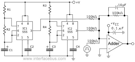
This circuit combines the outputs from two distinct 555 multivibrators using a summing operational amplifier (Op Amp). It serves to illustrate an alternative implementation of a 555 timer, with most background calculations addressed in other sections. The standard configuration...
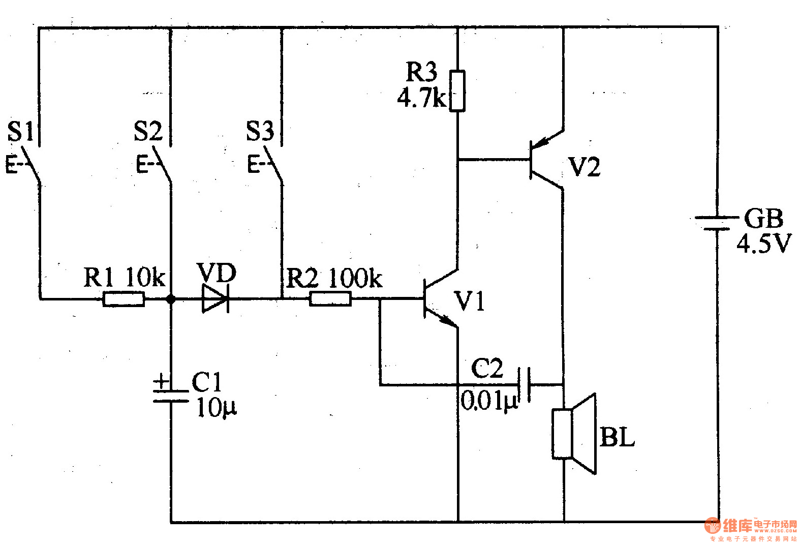
The three-tone electronic doorbell circuit includes buttons S1-S3, transistors V1 and V2, a speaker BL, resistors R1-R3, capacitors C1 and C2, a diode VD, and a battery GB, as illustrated in Figure 3-109. Resistors R1-R3 are 1/4W carbon film...
Upon acquiring the car, it was appreciated that it did not emit a "chirp" or sound the horn each time the doors were locked or unlocked. There are occasions when discreetness is preferred regarding entering or exiting the vehicle....
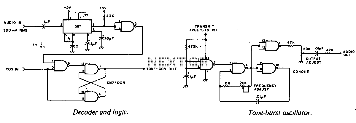
A tone burst sent at the beginning of each transmission is decoded at the receiver by a phase-locked loop (PLL), resulting in an output from pin 3 of a logic gate that activates a carrier-operated switch (COS). In this circuit,...
This simple tone control can be used in many audio applications. It can be added to amplifiers, used as a stand-alone control module, or even built into new and exciting instruments. Its one IC construction makes it a very...