
TV Pattern Generator (ZNA234E)
The ZNA234E integrated circuit serves as the core component of this circuit, capable of generating various test patterns essential for evaluating television display performance. The output from the ZNA234E is a composite video signal, which can be directly fed into a television receiver's video input. Alternatively, this signal can be utilized to drive a modulator, allowing for connection to the aerial socket of the TV, facilitating broader compatibility with different television models.
The circuit is designed to accommodate both CCIR and EIA standards, which are prevalent in different regions. By configuring pin 2 of the ZNA234E to ground, the output is adjusted to produce a 525-line video signal, adhering to the EIA standard. Conversely, connecting this pin to +5V enables the generation of a 625-line signal, suitable for CCIR-compliant televisions.
Two variable resistors, RV1 and RV2, are incorporated into the circuit design to provide user-adjustable parameters for the test patterns. RV1 is responsible for setting the vertical line width of the displayed patterns, allowing for customization based on the requirements of the testing environment or the specifications of the television being evaluated. RV2, while not explicitly detailed in the provided description, likely serves a complementary function, possibly adjusting horizontal line width or overall contrast levels of the test patterns.
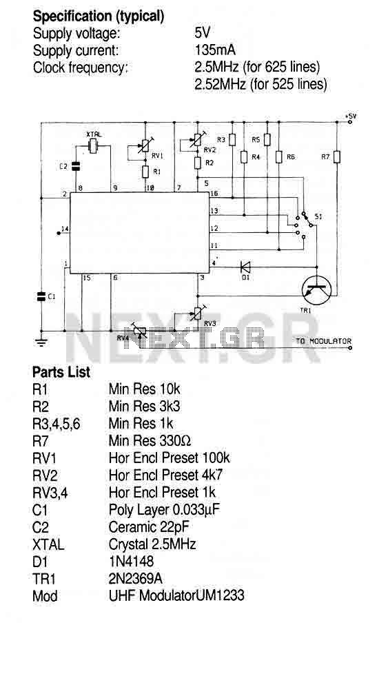
The circuit's design emphasizes flexibility and ease of use, making it a valuable tool for engineers and technicians involved in television servicing, testing, and calibration. The ability to produce multiple test patterns, including crosshatch, dot, and greyscale, enables comprehensive assessment of television display quality, ensuring that the visual output meets industry standards.This Circuit uses the ZNA234E IC which makes available all the waveforms necessary to produce the crosshatch, dot and greyscale test patterns on a television screen. The composite video output can be injected directly into the video input of a receiver or used to drive a modulator for connection to the aerial socket.
The circuit shown can be connected to a standard UHF TV set with 625 lines (CCIR standard), but by connecting pin 2 to ground instead of +5V, the output will produce 525 lines (EIA standard). In the circuit shown RV1 sets the vertical line width, RV2 sets 🔗 External reference
Related Circuits
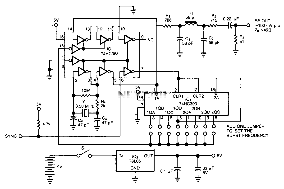
The circuit generates low-level RF bursts with frequencies up to 10 MHz, allowing for field testing of high-frequency receivers. A jumper-selectable binary fraction (1/2 to 1/256) of the Y1 crystal frequency gates the output RF signal. The output amplitude...

Utilize the Maxim MAX292 switched-capacitor filter integrated circuit to convert a square wave into a sine wave. The operational frequency range of the circuit spans from 5.2282 Hz to 8928.6 Hz when the microcontroller is functioning at a 16-MHz...
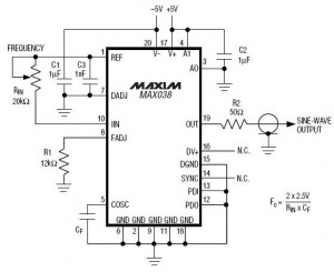
This circuit utilizes the versatile MAX038 function generator. While some advanced features of this IC are disabled in this configuration, it is capable of generating sine, triangle, and square waves by adjusting the A0 and A1 pins (refer to...
A high-frequency waveform generator is highly beneficial for electronic experimentation and design. This circuit generates sine wave oscillations; however, it can be modified to produce triangle or square wave functions. The frequency can be controlled using current. By disconnecting...
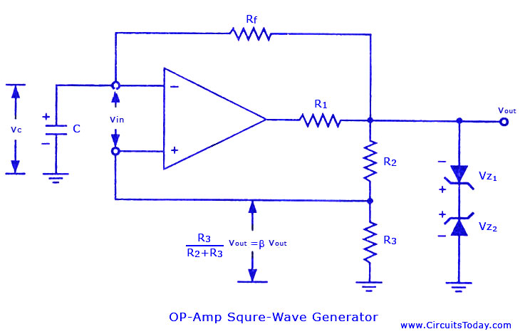
Non-sinusoidal waveform generators are also referred to as relaxation oscillators. The op-amp relaxation oscillator depicted in the figure functions as a square wave generator. Generally, square waves are relatively simple to generate. Similar to the UJT relaxation oscillator, the...
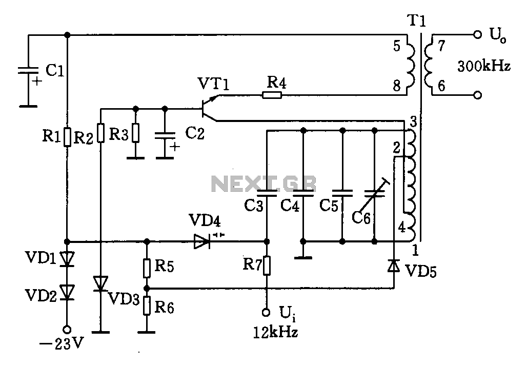
This circuit is designed for a 300 kHz signal generator. It includes components such as VT1, T1, VD4, and other associated elements. The voltage-controlled oscillator (VCO) employs an LC-tuned collector, with VT1 functioning as the oscillating transistor, varactor diode...