
Infrared burglar alarm circuit schematic

The infrared burglar alarm circuit is designed to detect unauthorized entry by utilizing a pair of infrared probes: an emitter and a receiver. The NE555 timer IC is configured in astable mode to generate a continuous square wave signal at a frequency of 40 kHz. This frequency is chosen to optimize the detection range and reduce interference from ambient light sources.
Resistors R1 and R2, along with capacitor C3, are critical in determining the frequency of oscillation. The values of these components can be adjusted to modify the duty cycle and frequency of the output signal, allowing for customization based on specific application requirements. The VLS infrared emission probe emits modulated infrared light, creating an invisible barrier. When an intruder interrupts this beam, the VDL infrared receiver probe detects the absence of the signal.
The output from the infrared receiver can be interfaced with additional circuitry, such as a microcontroller or alarm system, to trigger an alert or notification upon beam interruption. This circuit can be powered by a DC power supply, ensuring that it remains operational under various conditions. The design can be further enhanced by incorporating additional features, such as adjustable sensitivity, multiple beam paths for increased security, and integration with wireless communication modules to send alerts to a remote monitoring system.Infrared burglar alarm circuit schematic is shown in Figure 1. Infrared transmitter is a multivibrator with oscillation frequency being 40kHz, and it is composed of IC2 ( NE555 ), R1, R2 and C3. VLS is the infrared emission probe which can be used to radiate 40kHz high-frequency externally to form the IR beam.
VDL is the infrared receiver probe, and it form.. 🔗 External reference
Related Circuits
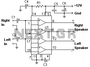
The 22-watt amplifier is straightforward to construct and cost-effective. This circuit can serve as a booster in a car audio system, an amplifier for satellite speakers in a surround sound or home theater setup, or as an amplifier for...
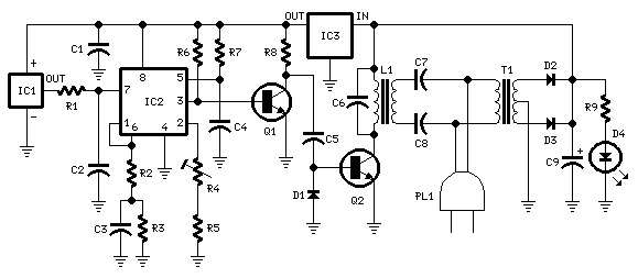
This circuit is intended for precision centigrade temperature measurement, with a transmitter section converting to frequency the sensor's output voltage, which is proportional to the measured temperature. The output frequency bursts are conveyed into the mains supply cables. The...
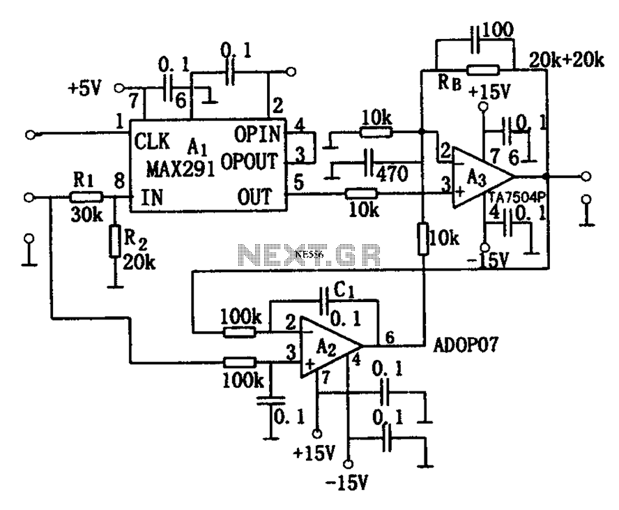
The circuit depicted in Figure 8 is a low-pass filter utilizing an eight-stage switched-capacitor configuration. The cutoff frequency of the circuit can be adjusted, with a clock frequency that can be modified to 1/100 of the original frequency. A...
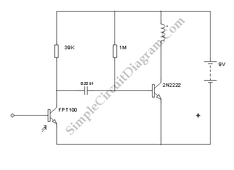
Configured with capacitive coupling by inserting a small capacitor between the phototransistor and the bipolar transistor, this relay circuit will respond only to rapid changes. This relay circuit utilizes capacitive coupling to enhance its responsiveness to fast signal changes. The...
The circuit involves a switch (S1) that facilitates the release of current when it reaches the shut-off mechanism. The circuit operates by utilizing a switch (S1) that plays a crucial role in controlling the flow of current within the system....
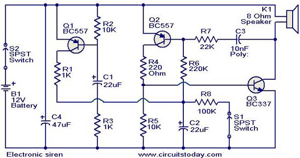
This is a compact electronic siren circuit based on three transistors. This circuit is suitable for incorporation with other alarm or siren projects such as burglar alarms, automatic factory sirens, or a simple push-to-on alarm. The electronic siren circuit...