
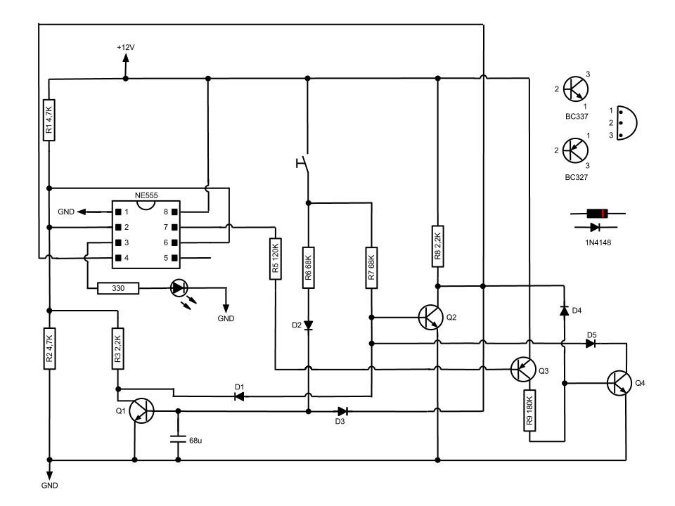
Touch switch

The NE555 timer in monostable mode is designed to produce a single output pulse of a specified duration in response to a triggering event. In this configuration, the timer is activated by a momentary low signal at the trigger input (pin 2), which is normally held high by the 22-ohm resistor. The value of the resistor is critical as it establishes the baseline voltage level for the triggering condition.
When the operator touches the contact plates, the lower skin resistance effectively decreases the impedance, allowing the voltage at pin 2 to drop below the threshold level required to trigger the timer. This action activates the internal timing mechanism, causing the output at pin 3 to go high for a duration defined by the time constant, which is determined by the resistor (R1) and capacitor (C1) connected to the circuit.
The output pulse width, calculated as 1.1 times the product of R1 and C1, is set to approximately 5 seconds in this design. This time period can be adjusted by changing the values of R1 and C1, allowing for flexibility in the operation of the circuit.
In applications where a relay is preferred, the output from pin 3 can be connected to a relay instead of the standard LED and resistor configuration. This modification allows the circuit to control higher power loads or perform switching functions in various electronic applications. The relay will be activated for the duration of the output pulse, providing a practical means to control devices such as lights, motors, or other electrical components.
Overall, this NE555 monostable timer circuit provides a reliable solution for generating timed output pulses, with user-friendly triggering and versatile output options.The circuit is basically a NE555 monostable, the only major difference being its method of triggering. The trigger input is biased to a high value by the 22 ohm resistor. When the contact plates are touched, the skin resistance of the operator will lower the overall impedance from pin 2 to ground.
This action will reduce the voltage at the trigger input to below the 16 Vcc trigger threshold and the timer will start. The output pulse width will be = 1.1 R1C1, in this circuit about 5 seconds. A relay connected from pin 3 to ground instead of the LED and resistor could be used to perform a switching function.
Related Circuits
This circuit, based on the NE555 timer IC, toggles the output on and off using a momentary switch. It functions similarly to a mechanical latching relay but resets to its initial state when the power supply is turned off....
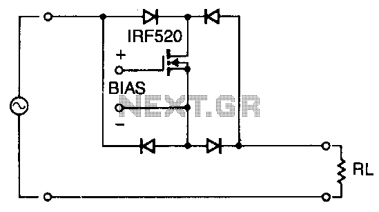
Utilizing four diodes in an array enables the use of a single MOSPOWER transistor for analog switching. The current flow is managed by maintaining the source-base connection of the MOSFET towards the load. It is essential to select diodes...
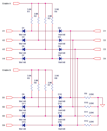
This circuit represents a low-cost printer sharing device that was developed some time ago. The product was encapsulated in epoxy with a black dye and had a limited commercial release. The output impedance of this circuit is high, with...
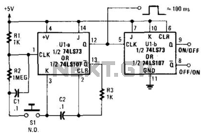
A 7473 JK flip-flop U1A is configured as a monostable multivibrator to drive U1B, functioning as a switch debouncer. The circuit features a self-clearing mechanism during power-up, providing a 100-ms pulse at pin 12 of U1A. The circuit utilizes the...
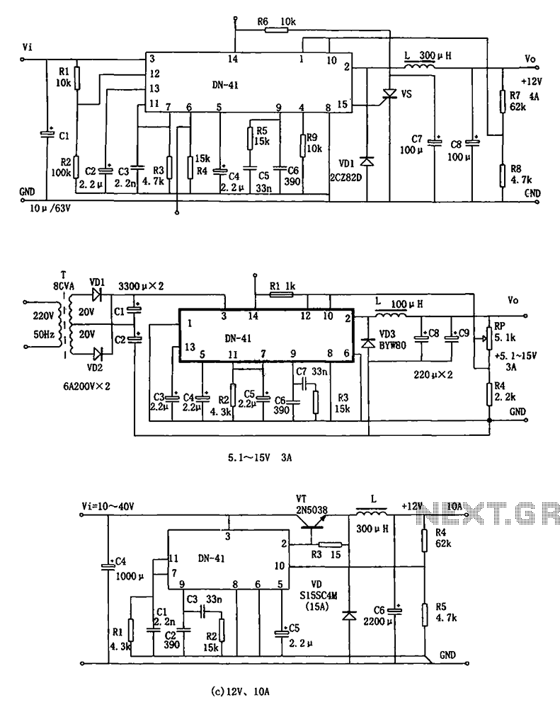
The DN-41 is a high-current switching regulator that includes an overcurrent and overvoltage (crowbar) protection circuit, a reset circuit, and a soft start feature. It is designed to operate with fewer external components while maintaining stability, safety, and reliability....
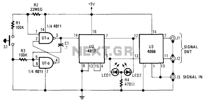
The A/B switch circuit comprises three integrated circuits (ICs) and several resistors. Two gates from a 4011 quad 2-input NAND gate (U1A and U1B) are configured as a monostable multivibrator. When switch SI is activated, it triggers a 4017...