
touch switch circuit diagram
The described circuit operates as a water level indicator and alarm system that utilizes a combination of resistors, switches, LEDs, and a transistor to monitor the water level within a tank. At the core of the circuit is a 180K ohm resistor used to maintain the state of the switch when the tank is devoid of water. This resistor ensures that when the tank is empty, the voltage at the switch remains low, keeping the switch open and preventing any LEDs from illuminating.
As water begins to fill the tank, it creates a conductive path between the wire connected to switch S1 and the positive voltage supply. This action closes switch S1, allowing current to flow and illuminating LED1, indicating that the water level has reached a certain threshold. The progressive filling of the tank triggers a series of additional LEDs (LEDs 2, 3, and 4) to light up sequentially, providing a visual representation of the increasing water level. This cascading illumination can serve as an effective visual alert for users.
When the water level reaches its maximum capacity, it applies sufficient voltage to the base of the BC148 transistor. This causes the transistor to enter saturation, allowing a larger current to flow through the buzzer circuit, thereby activating the buzzer. The buzzer serves as an audible alarm to notify users that the tank is full, preventing overflows.
To deactivate the buzzer, an SPST (Single Pole Single Throw) switch is included in the circuit. This switch must be opened to interrupt the current flowing through the buzzer circuit, silencing the alarm. The simplicity of this design makes it suitable for various applications in water management systems, ensuring that users are promptly alerted to water levels while also providing a clear visual indication through the LEDs.When the water is empty the wires in the tank are open circuited and the 180K resistors pulls the switch low hence opening the switch and LEDs are OFF. As the water starts filling up, first the wire in the tank connected to S1 and the + supply are shorted by water.
This closes the switch S1 and turns the LED1 ON. As the water continues to fill the tank, the LEDs2, 3 and 4 light up gradually. When the water is full, the base of the transistor BC148 is pulled high by the water and this saturates the transistor, turning the buzzer ON. The SPST switch has to be opened to turn the buzzer OFF. 🔗 External reference
Related Circuits
A soft power switch for a microcontroller is designed such that a momentary switch can activate the circuit, including the microcontroller. When the switch is pressed a second time, the microcontroller is capable of shutting itself down after executing...
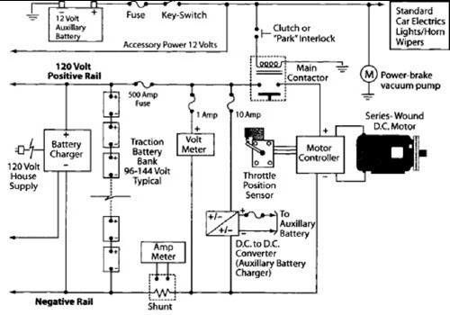
After charging the batteries for many hours with the 12V charger and PowerCheqs, a drive of about 5 miles resulted in the low battery light activating. The PakTrakr indicated that the battery adjacent to the most positive battery required...
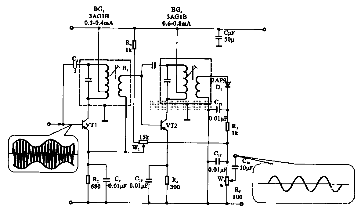
The demodulation and detection circuit is a radio AM intermediate frequency (IF) signal amplifier that performs two-stage detection using diode Dr. It extracts the audio signal from the IF carrier detection and subsequently sends it to the power amplifier...
This cable TV amplifier circuit is an RF amplifier designed for quick installation between two coaxial cables. Both the input and output impedances are compatible with 75-ohm cables. The main amplifier is the T1 transistor, while T2 functions as...
This circuit serves as a dependable alternative to thermally-activated switches designed for flashing Christmas tree lamps. The arrangement consisting of Q1, Q2, and associated resistors activates the silicon-controlled rectifier (SCR). The timing function is determined by resistors R1, R2,...
A DIY GSM jammer schematic diagram designed for use with GSM1900, operating within the frequency range of 1930 MHz to 1990 MHz. The GSM jammer circuit is intended to disrupt communication between mobile phones and base stations within the specified...
Warning: include(partials/cookie-banner.php): Failed to open stream: Permission denied in /var/www/html/nextgr/view-circuit.php on line 713
Warning: include(): Failed opening 'partials/cookie-banner.php' for inclusion (include_path='.:/usr/share/php') in /var/www/html/nextgr/view-circuit.php on line 713