
Touch Switch I
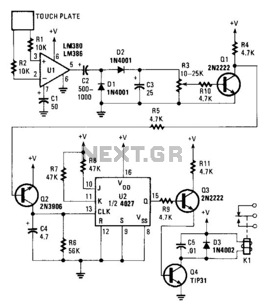
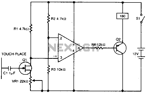
The circuit described operates as a touch-sensitive switch, leveraging the capacitive coupling of the human body to detect the presence of a finger. The LM380 or LM386 audio power amplifier amplifies the weak 60-Hz signal picked up by the metal plate. The rectification process performed by diodes D1 and D2 converts the AC signal into a DC voltage, while capacitor C3 smooths out any fluctuations, ensuring a stable voltage for subsequent stages.
Potentiometer R3 is crucial for setting the sensitivity of the switch. By adjusting R3, the user can determine the minimum trigger voltage required to activate Q1. When Q1 is triggered, it allows current to flow through R4, effectively pulling its collector towards ground. This action sends a signal to Q2, which functions as a clock generator for the flip-flop.
The 4027 flip-flop is configured for toggle operation, allowing it to change its output state with each pulse from Q2. The J and K inputs are tied high, while the set and reset inputs are held low to ensure that the flip-flop toggles with each clock pulse, providing a reliable mechanism for switching states.
Transistor Q3 serves as an intermediary, amplifying the output from the flip-flop before driving Q4, the relay driver. The 4.7 kΩ resistor between Q3 and the flip-flop output limits the current, ensuring that Q3 operates within safe parameters. Q4, as the relay driver, controls the actual load, whether it be lights or appliances, while adhering to the specified relay ratings to prevent damage from excessive current. This touch-sensitive switch design effectively combines capacitive sensing with transistor switching to provide a practical solution for controlling electrical devices. This switch reacts to the touch of a finger to turn lights and/or appliances on or off. The device uses the human body as an antenna to pick up 60-Hz hum, which is applied to a metal plate by your finger. The signal is fed to the input of Ul, an LM380 audio-power amplifier. An LM386 should work as well. The 60-Hz output from the amplifier is rectified by Dl and D2, then filtered by C3. Potentiometer R3 sets the trigger voltage used to saturate Ql. When Ql turns on, the collector end of R4 goes almost to ground and provides the needed voltage to turn on Q2. Transistor Q2 turns on and clocks. The flip-flop is configured for toggle-mode operation, so its output switches states with each clock pulse.
The 4027 (U2) is wired to toggle by tying the J and inputs high and the set and resets low. Transistor Q3 is connected to the Q output through the 4.7-KOhmhm resistor. Transistor Q3 drives Q4, the relay driver. Be sure that the load does not exceed the relay ratings. 🔗 External reference
Related Circuits
Hall-effect switches offer multiple benefits compared to mechanical and optically coupled switches. They are unaffected by ambient light and dirt, do not jam, and do not experience mechanical wear. The primary disadvantage is that each device typically requires three...
This circuit is beneficial for applications where a load must be activated from one location and deactivated from another. Multiple momentary normally open (N/O) switches or push buttons can be connected in parallel. The circuit described facilitates remote control of...
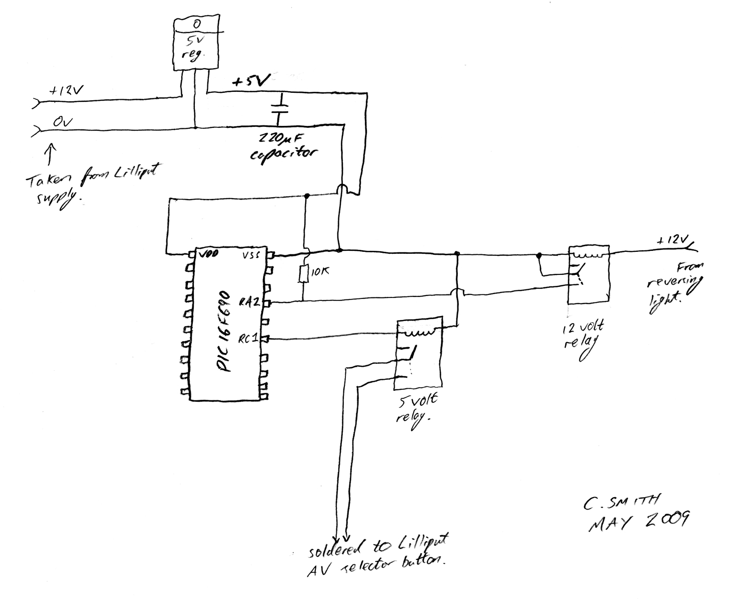
There have been numerous discussions regarding the Lilliput's inability to automatically switch, despite the presence of this feature in the secret menu. The Lilliput display is a versatile device often used in various applications, including professional video production and...
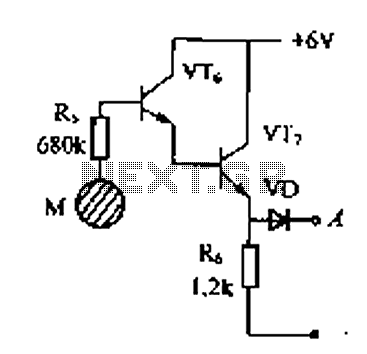
Delay electronic doorbell circuit - touch doorbell amplifier circuit The delay electronic doorbell circuit is designed to provide a user-friendly interface for doorbell activation, utilizing a touch-sensitive amplifier circuit. This circuit typically incorporates a touch sensor that detects user interaction,...
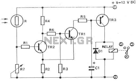
The circuit is a light switch that activates when the light intensity drops on a photoresistor. It features a straightforward construction and can be utilized in numerous applications. The photoresistor and the trimmer function as a voltage divider and...
A high impedance input is provided by Q1, a general-purpose field effect transistor. The 741 operational amplifier is utilized as a sensitive voltage level switch, which subsequently activates Q2, a medium current PNP bipolar transistor. This action energizes a...