
Touch Switch with relay
Part List
R1=10M 1/4W 5% [See Text] R6=1K 1/4W 5% D2=3.9V 0.4W ZENER
R2-3=1M 1/4W 5% C1-2=470nF 63V MKT D3=LED RED
R4=33K 1/4W 5% C3=47nF 63V MKT Q1=BD679
R5=1.8K 1/2W 5% C4=22uF 25V IC1=4011
D1=1N4148 RL1=12V Relay
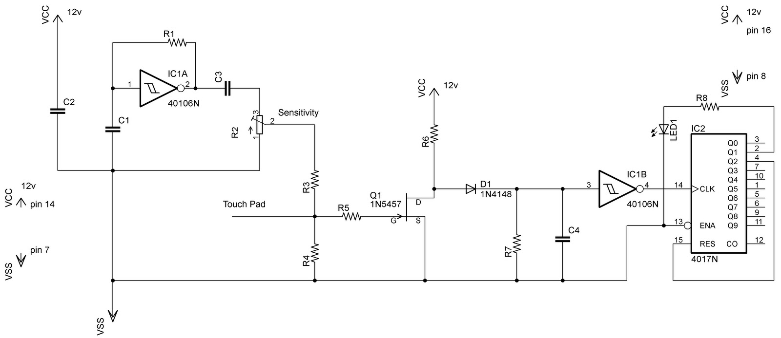
The circuit described is a simple touch-activated relay control system. The primary function is to toggle the state of relay RL1, which can control various loads or devices connected to its contacts. The activation mechanism relies on a small metal surface that, when touched, triggers the circuit.
The power supply for the entire circuit is +12V, which is suitable for energizing the relay RL1, rated for 12V operation. The heart of the control logic is the integrated circuit IC1, which is a quad 2-input NAND gate (CD4011), functioning here to process the signal from the touch sensor.
The voltage supply for IC1 is regulated to 3.9V using a zener diode (D2) in conjunction with resistor R5. This voltage regulation is crucial as it ensures that the logic levels are compatible with the operation of the IC. The combination of R5 and D2 forms a simple voltage divider and clamping circuit, which stabilizes the voltage supplied to the IC.
The touch-sensitive input is likely connected to the gate of transistor Q1 (BD679), which acts as a switch to control the relay. When the metal surface is touched, it creates a low-resistance path that allows current to flow, turning on the transistor. This, in turn, energizes the relay coil, closing the contacts of RL1.
LED D3 serves as an indicator for the state of the relay. When RL1 is energized, D3 lights up, providing a visual cue that the relay contacts are closed. This is useful for confirming the operation of the circuit without needing additional testing equipment.
Resistors R1, R2, R3, R4, and R6 are used to set the biasing and gain conditions for the circuit components, ensuring proper operation. Capacitors C1, C2, C3, and C4 are included for filtering and stability, helping to reduce noise and provide a stable operation.
In summary, this circuit offers a straightforward solution for touch-activated control of a relay, with visual feedback provided by an LED, and is designed with common electronic components that ensure reliability and ease of assembly. Adjustments to resistor values, particularly R1, may be necessary to fine-tune sensitivity and performance based on specific application requirements.A simple circuit with which we have the possibility opening and closing the RL1 contacts. He becomes touching a small metal surface. Clue of situation that is found RL1, is become by the Led D3. The supply of circuit is +12V, the IC1 is supplied with 3.9V fall of voltage that is ensured by combination R5 and zener D2. For more good restoration perhaps it should adaptation of R1 value. Part List R1=10M 1/4W 5% [See Text] R6=1K 1/4W 5% D2=3.9V 0.4W ZENER R2-3=1M 1/4W 5% C1-2=470nF 63V MKT D3=LED RED R4=33K 1/4W 5% C3=47nF 63V MKT Q1=BD679 R5=1.8K 1/2W 5% C4=22uF 25V IC1=4011 D1=1N4148 RL1=12V Relay 🔗 External reference
Related Circuits
Switch mode circuits can implement a lead acid battery charger more efficiently. It can be constructed using the bq24105 battery charger controller. The bq24105 was originally designed to charge single, two, or three-cell Li-polymer and Li-ion battery packs. However,...

Mindsensors produces an excellent RCX sensor multiplexer for the NXT, known as the RXMux, which enables the connection of up to four RCX-style analog sensors to the NXT. The RXMux supports various sensors. Due to the frequent use of...
In the previous post regarding a capacitive touch switch, the output was activated only while the touch was maintained. This means that the circuit would drive the load only during the touch, and once the touch was removed, it...
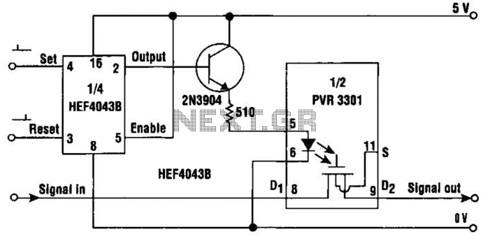
This simple circuit provides a solid-state equivalent of the electromechanical latching relay. The switching mechanism is clean, highly resistant to vibration and shock, and is not sensitive to magnetic fields or position. The circuit operates as follows: a set...
All files are found using legitimate search engine techniques. This site does not condone hacking into sites to create the links it lists. It is assumed that all links found on the search engines used are obtained legally and...
It was one of those days when learning chemistry, philosophy, and literature seemed necessary. Contemplating my plans for the day, I decided to embark on a project that I had wanted to undertake for a long time but had...
Warning: include(partials/cookie-banner.php): Failed to open stream: Permission denied in /var/www/html/nextgr/view-circuit.php on line 713
Warning: include(): Failed opening 'partials/cookie-banner.php' for inclusion (include_path='.:/usr/share/php') in /var/www/html/nextgr/view-circuit.php on line 713