
Touch-type FET stepless dimmer
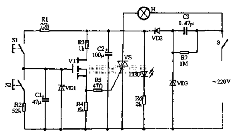
The described circuit utilizes a capacitive half-wave rectifier configuration to convert AC voltage to a lower DC voltage suitable for powering low-energy devices. The capacitors C2 and C3 serve to smooth the output voltage, ensuring a stable DC supply. The diodes VD2 and VD3 are crucial for the rectification process, allowing current to flow in one direction while blocking reverse current, thus preventing damage to the downstream components.
The control mechanism of the circuit is implemented through switch S, which acts as a primary control element. This switch can be a conventional toggle switch for manual operation or a touch-sensitive switch concealed within a lamp fixture for aesthetic purposes. In the default state, the switch remains open, keeping the lamp off and conserving energy. When the user desires illumination, they can activate the touch switch by placing a designated object, such as a small doll, on it. This action closes the circuit, allowing current to flow and powering the lamp.
Further control of brightness is facilitated by switches S1 and S2, which are designed to adjust the light intensity based on user interaction. S1 increases brightness, while S2 decreases it, providing a user-friendly interface for ambient light control. The inclusion of an LED indicator serves as a visual cue, indicating the operational status of the circuit, enhancing usability and ensuring users are aware of the system's state.
Overall, this circuit design exemplifies a practical application of capacitive power supply technology, integrating user-friendly control features and ensuring efficient power management for lighting applications. Capacitors C2, C3, diode VD2, VD3 and other components simple capacitive half-wave rectifier buck power supply, the entire supply control circuit of electricity, the power supp ly by the switch S off control It can be an ordinary small toggle switch, can also be hidden in a lamp on the touch panel key switch, usually switch S open, lamp is not lit, turn on the lights when needed, as long as it is placed on a small doll above, the pressure switch contact is closed, the circuit that is energized work. SI, S2 are respectively used to brighten and dim the touch of a button switch, LED indicator for the circuit.
Related Circuits
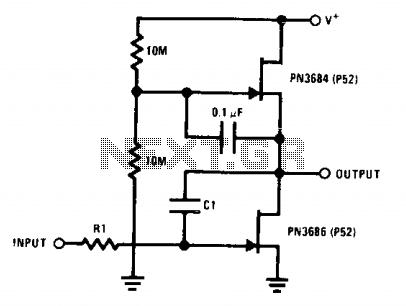
This circuit employs the "µ-amp" technique to achieve a very high voltage gain. By using a CI in the circuit as a Miller integrator or capacitance multiplier, this simple configuration can manage very long time constants. The described circuit primarily...
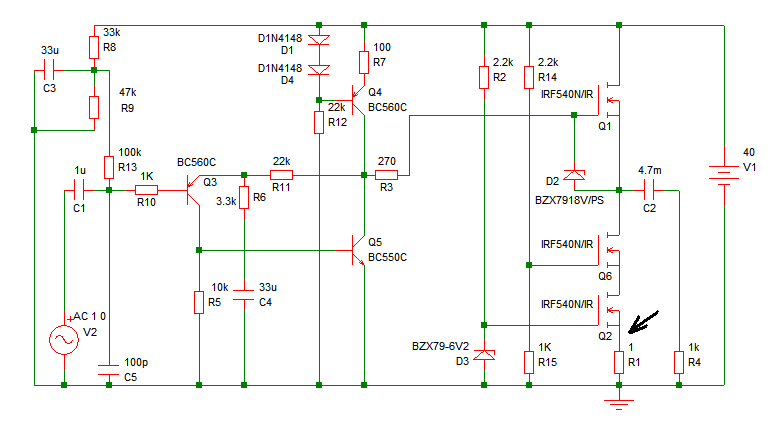
Increasing the quiescent current (Iq) will result in more power output at 4 ohms. It is understood that decreasing the supply voltage affects performance. Increasing the quiescent current (Iq) in a circuit can lead to enhanced power output, particularly when...

A project is underway to create a custom electronic circuit for a 1969 Chevelle. The design aims to replicate a retained accessory power feature similar to a product offered by Dakota Digital, but at a lower cost. The circuit...
ESP Lighting Information Page - Dimmers, electronic transformers, etc. - how they work, what is wrong with them, and how it can be fixed. The ESP Lighting Information Page provides insights into various lighting components, specifically focusing on dimmers and...
An ideal solution for making a good, low-cost power amplifier. It's an ideal solution for creating a home cinema system. The preamplifier and the driver are supported in an operational amplifier [IC1]. The voltage drop in resistors R5 and...
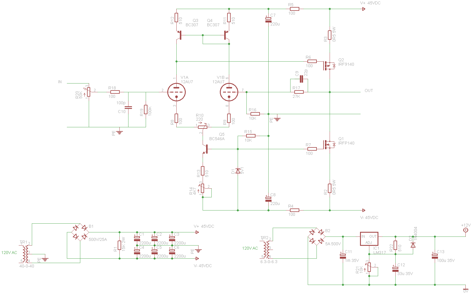
A tube/MOSFET hybrid power amplifier is being constructed based on a circuit published in AudioXpress by Cozza (May 2001), which is derived from a design by Borbely. The tube/MOSFET hybrid power amplifier integrates the warm, rich sound characteristics of vacuum...