
dome light dimmer

The circuit design incorporates a standard 555 timer IC, which is widely used for timing applications. The configuration is set in monostable mode, where a trigger signal on pin 2 initiates the timing cycle. When the circuit is activated, the capacitor C2 begins to charge through the resistor R4. The time duration for which the output at pin 3 remains high can be calculated using the formula:
\[ T = 1.1 \times R4 \times C2 \]
where T is the time in seconds, R4 is the resistance in ohms, and C2 is the capacitance in farads. The choice of values for R4 and C2 will directly affect the performance of the circuit, allowing for customization based on the specific requirements of the retained accessory power feature.
Additionally, the circuit may include a diode for reverse polarity protection and a power supply input that can be connected to the vehicle's battery. Proper decoupling capacitors should be added near the power supply pins of the 555 timer to ensure stable operation. The output from pin 3 can be connected to a relay or transistor, allowing the control of higher current loads, such as the vehicle's accessory systems.
This design provides a cost-effective solution for integrating a retained accessory power feature into vintage vehicles, enhancing functionality while maintaining a classic aesthetic.I am building this for my 1969 Chevelle. Dakota Digital has something similar, but I didn`t want to spend $200 onit. Iam working on replicating the retained accessory powertoo. The capacitor (C2) & resistor (R4) connected to pins 6 & 7on the 555 timer controls how long the output on pin 3is high. Alarger capacitor or more resistance will give you moretime. 🔗 External reference
Related Circuits
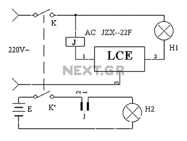
The application circuit operates the device as illustrated below, allowing for intermittent lighting in specific situations (e.g., during surgery). It utilizes an LCE module for blackout emergency lighting, which activates automatically after a power failure, ensuring uninterrupted illumination. In...

This automatic light dimmer circuit enables controlled lighting that gradually turns on or off. The operation is as follows: when switch S1 is closed, capacitor C1 charges slowly. Once the voltage across C1 reaches 0.6 volts, transistor T1 begins...
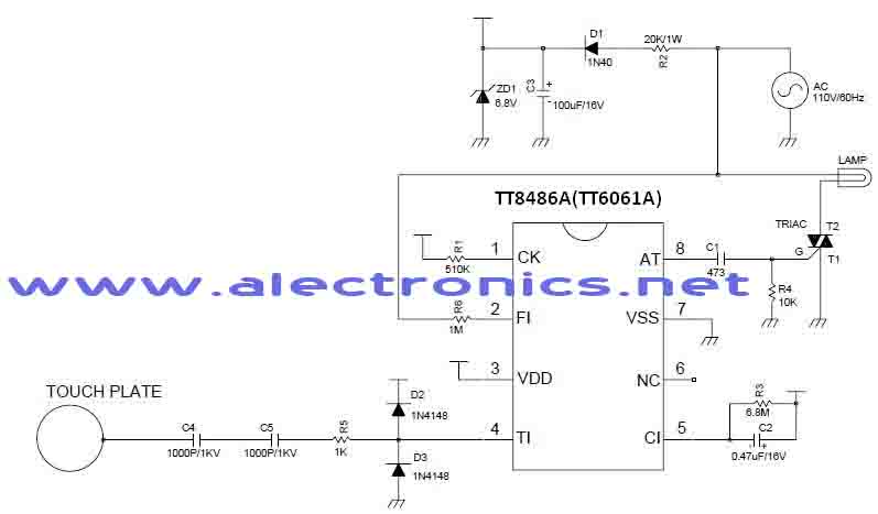
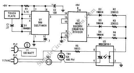
A simple dimmer circuit can be constructed using the CMOS ICs TT8486A and TT6061A, allowing control over the intensity of an incandescent lamp through a touch contact. This electronic touch dimmer can increase the brightness of incandescent lamps in...
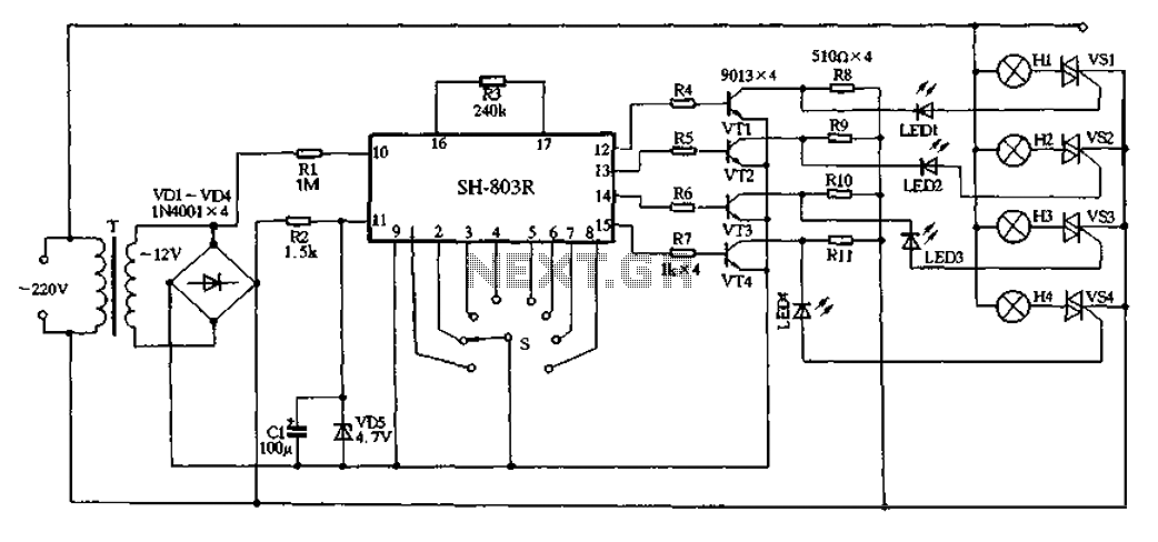
22V AC is supplied through thyristors VSl to VS4 for lighting control. The current is routed through transformer T, followed by rectification using diodes VD1 to VD4, and regulated by VD5 to provide a filtered output of approximately 4.7V...
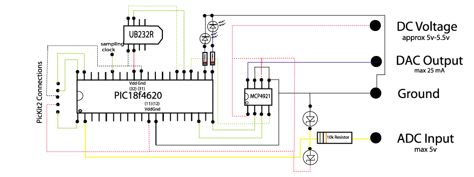
The circuit below demonstrates how to construct a DAQ_LITE device, accompanied by an image of the finished PCB board. It is important to note that the 80mA fuse depicted in the image and the nearby protection diode are recommended...
This is a three-mode lamp dimmer circuit with touch control. This circuit can be used to control a lamp in three operation modes: dim, off, and bright. It utilizes a NE555 timer. The three-mode lamp dimmer circuit designed with touch...