
Pavels MOSFET Follower

Increasing the quiescent current (Iq) in a circuit can lead to enhanced power output, particularly when driving a load of 4 ohms. Quiescent current is the current flowing through a transistor or amplifier when no input signal is present. By increasing Iq, the amplifier operates in a more linear region, which can improve efficiency and reduce distortion, thereby allowing for greater power delivery to the load.
When the supply voltage is decreased, it impacts the maximum output power that can be delivered to the load. The relationship between supply voltage, quiescent current, and load impedance is crucial in amplifier design. A lower supply voltage limits the headroom available for the output signal, which can lead to clipping and reduced dynamic range. Therefore, while increasing Iq can improve performance, it is essential to balance this with the supply voltage to ensure optimal operation.
In practical applications, designers often utilize feedback mechanisms to stabilize the quiescent current and maintain linearity across varying load conditions. This can involve the use of resistors, current mirror circuits, or specialized biasing techniques to achieve the desired Iq without compromising the overall efficiency of the amplifier. Additionally, thermal considerations must be taken into account, as higher quiescent currents can lead to increased heat dissipation, necessitating adequate thermal management solutions.
Overall, the interplay between quiescent current, supply voltage, and load impedance is a fundamental aspect of amplifier design that directly influences performance characteristics such as output power, distortion, and thermal stability.Originally Posted by shaan Increasing Iq will result in more 4ohm power? Ya I think I understand now. Ya, once I decreased the supply voltage and.. 🔗 External reference
Related Circuits
This circuit falls under the category of an astable multivibrator. It is designed to test N-channel MOSFETs, specifically power types such as the IRF830, to determine their functionality. The astable multivibrator circuit is a type of oscillator that continuously switches...

The circuit does not guarantee the testing of all defective MOSFETs or all fault conditions in MOSFETs. If the MOSFET is functional, it will operate within the astable multivibrator circuit, resulting in the LED flashing. The described circuit employs an...

A hybrid amplifier is being developed, utilizing an Aikido configuration for the voltage amplification stage (VAS) and an emitter-follower variation for the output stage (OPS). The hybrid amplifier design integrates two distinct amplification stages to achieve high performance and...
Currently, a basic MOSFET amplifier or power amplifier is designed to deliver an output power of ±100 Watts RMS with an 8 Ohm load, or ±160 Watts RMS with a 4 Ohm load. The simplicity of this circuit results...
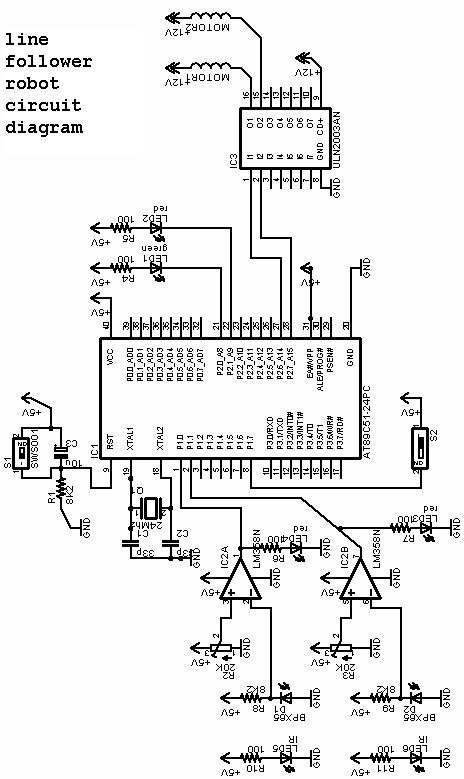
The project involves a line follower robot utilizing the 8051 microcontroller, accompanied by a circuit diagram. A full project report on the line follower or chaser robot is available for download. The line follower robot is designed to autonomously navigate...
A bicycle light control circuit that reads various buttons and sets multiple outputs such as headlights, taillights, and blinkers. The design utilizes an ATtiny24 microcontroller, operating at an internal oscillator frequency of 8 MHz, and is programmed in C...