
Transistor Checker Circuit
The circuit utilizes a 741 operational amplifier, which is a widely used component in analog electronics due to its versatility and reliability. The op amp is configured as a voltage follower, meaning that the output voltage directly follows the input voltage, resulting in no amplification but providing high input impedance and low output impedance. This characteristic is particularly useful in applications where signal buffering is required.
The use of a 50-meter movement indicates that the circuit is intended for applications requiring a visual representation of voltage levels, such as in analog voltmeters. The potentiometer R7 allows for fine-tuning of the zero point on the meter, ensuring accurate readings across the entire scale. Potentiometer R6 is critical for setting the full-scale reading, allowing the user to calibrate the meter to the desired maximum voltage range.
Calibration procedures are essential for ensuring the accuracy of the voltmeter. The initial step of setting R6 to the mid-position with no input helps establish a baseline for the meter's operation. Adjusting R7 to zero the meter ensures that the device can accurately measure voltages around the zero point, which is crucial for applications involving both positive and negative voltages. By applying a known voltage of 1 Vdc and adjusting R6 accordingly, the user can ensure that the meter provides accurate full-scale readings, thereby enhancing the reliability of the measurements taken.
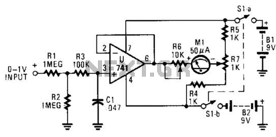
The ability to adjust the voltmeter to read both positive and negative voltages expands its functionality, making it suitable for a wider range of applications. This dual capability is achieved through careful adjustment of R7, which centers the scale and allows for accurate readings regardless of the polarity of the input voltage. Overall, the described circuit is an effective and efficient solution for voltage measurement tasks in various electronic applications. The circuit is built around a 741 general-purpose op amp that is configured as a voltage follower; with the components shown, the op amp has a voltage gain of one. The output of the 741 is used to drive a 50- meter movement. Potentiometer R7 is used to zero the meter and R6 sets the meter`s full-scale reading, Calibrating the meter is a snap.
With no input applied to the circuit, set R6 to mid-position and adjust R7 to zero the meter. Once that is done, apply a positive 1-Vdc voltage to the input and adjust R6 for a full-scale reading. The voltmeter can be adjusted to read both positive and negative voltages by adjusting R7 for a center scale reading at the meter`s zero position and a positive 1- V reading at the meter`s full-scale position. 🔗 External reference
Related Circuits
The transmitter described here includes an additional RF power amplifier stage following the oscillator stage, which increases the output power to 200-250 milliwatts. When connected to a properly matched 50-ohm ground plane antenna or a multi-element Yagi antenna, this...
A simple electronic lock circuit that requires minimal materials for its construction. This electronic lock circuit is designed for ease of assembly and functionality, making it suitable for various applications where secure access control is necessary. The circuit typically comprises...
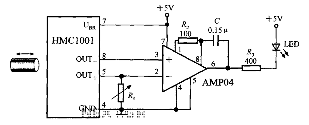
The circuit depicted in the figure includes the HMC1001 magnetic sensor, an operational amplifier (AMP04), and a light-emitting diode (LED), forming a proximity switch circuit. In this application, the operational amplifier functions as a comparator. When a magnet, approximately...
An H-bridge is a type of circuit utilized for controlling the direction (and occasionally the speed) of an electric motor by employing a single polarity voltage. The circuit functions by reversing the current flow to change the motor's rotation...
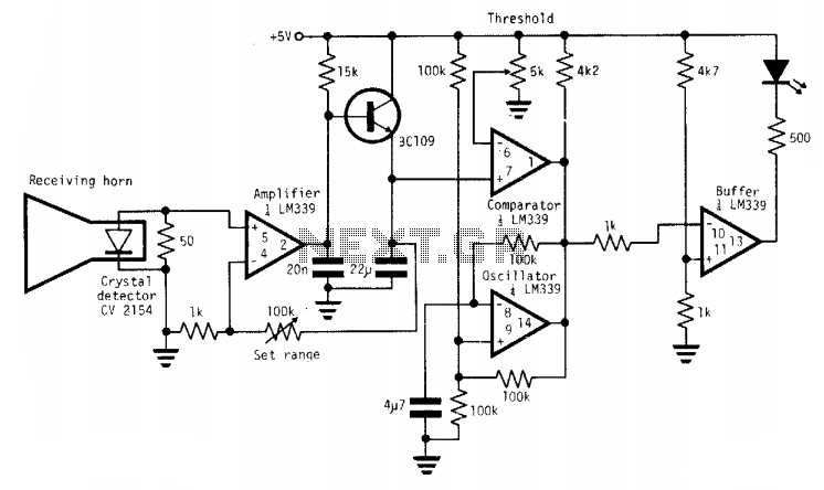
A simple X-band radar detector can indicate changes in RF radiation strength at levels as low as 2 mW/cm². When radiation strikes the detector diode, it generates a voltage at the input of an amplifier. The gain of this...
The MICRF112 is a high-performance, user-friendly, single-chip ASK/FSK transmitter integrated circuit (IC) designed for remote wireless applications within the 300 to 450 MHz frequency band. This transmitter IC features a true data-in, antenna-out configuration. The MICRF112 excels in three...