
One-chip radar detection circuit
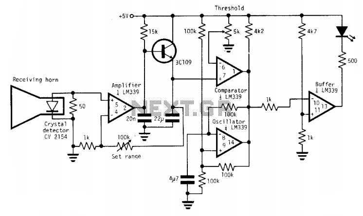
The X-band radar detector circuit operates by detecting RF radiation and converting it into a usable signal. The detector diode is the initial sensing element, which responds to incoming RF radiation. When RF energy is present, it generates a small voltage proportional to the radiation strength. This voltage is fed into a variable gain amplifier, allowing for sensitivity adjustments to ensure that the detector can operate effectively across various environmental conditions.
The output from the amplifier is then routed to a voltage comparator. This comparator compares the amplified signal against a preset threshold value that can be adjusted to prevent false triggering. The threshold is critical, as it determines the minimum level of RF radiation required to activate the warning system. The comparator's output is binary, providing a high signal when the input exceeds the threshold and a low signal otherwise.
In addition to the comparator, the circuit includes an oscillator configured to produce a square wave signal at a frequency of 2 Hz. This oscillator is connected in a wired-OR configuration with the comparator output. The wired-OR configuration allows for multiple signals to influence the output state. When no RF signal is detected, the comparator output remains low, which keeps the oscillator disabled and the lamp off.
Upon detection of RF radiation, the comparator output transitions to a high state, which releases the inhibition on the oscillator. As a result, the oscillator begins to operate, generating a square wave output that drives the lamp. The lamp thus flashes on and off at a rate of 2 Hz, providing a visual indication of the detected RF radiation. This flashing mechanism not only alerts the user to the presence of RF radiation but also serves as a clear warning signal that can be easily noticed.
Overall, this simple X-band radar detector circuit effectively combines RF detection, signal amplification, and visual indication in a compact design, making it suitable for various applications where RF radiation monitoring is essential.A simple X-band radar detector is capable of indicating changes in rf radiation strength at levels down to 2 mW/cm2. Radiation falling on the detector diode, produces a voltage at the input of an amplifier whose gain may be adjusted to vary the range at which the warning is given.
The amplifier output drives a voltage comparator with a variable threshold set to a level that avoids false alarms. The comparator output is connected in the wired-OR configuration with the open collector output of an oscillator running at a frequency of 2 Hz.
In the absence of a signal, the comparator output level is low, inhibiting the oscillator output stage and holding the buffer so the lamp is off. When a signal appears, the comparator output goes high, removing the lock from the oscillator which free-runs, switching the lamp on and off at 2 Hz.
🔗 External reference
Related Circuits

The D2025 is a dual audio power amplifier circuit designed as a stereo audio power amplifier integrated circuit. It comes in a DIP16 package and is applicable for various portable devices, such as tape recorders or portable stereo systems....

This is a measurement circuit designed to measure forces ranging from 0 to 1500 grams, producing an output voltage of 0 to 1500 millivolts (mV) with a sensitivity of 1 mV per gram. The circuit is powered by a...
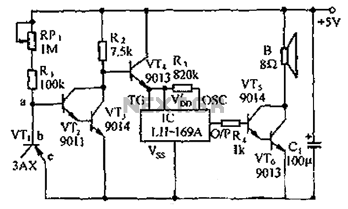
The circuit consists of a temperature sensor, electronic switches for temperature control, and a vocal language output system. During hot summer months, the central processing unit (CPU) of PCs frequently experiences overheating. The circuit, with VT1 positioned near the...

This combination sync stripper and universal video interface can solve various problems, including interfacing Super Nintendo with other devices, video overlay, and locking TV frames for scopes. Kits, fully tested units, and custom cable assemblies are available through Redmond...

This design circuit is intended for sine wave oscillators, providing both sine and square wave outputs across a frequency range from below 20 Hz to above 20 KHz. The oscillation frequency can be easily adjusted by changing a single...
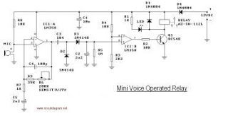
This circuit diagram represents a voice-operated relay. It functions similarly to a sound-activated switch circuit, which activates or deactivates the switch based on sound input. The output switch of this circuit operates through a relay. The voice-operated relay circuit typically...
Warning: include(partials/cookie-banner.php): Failed to open stream: Permission denied in /var/www/html/nextgr/view-circuit.php on line 713
Warning: include(): Failed opening 'partials/cookie-banner.php' for inclusion (include_path='.:/usr/share/php') in /var/www/html/nextgr/view-circuit.php on line 713