
Transistor Class A Power Amplifier
In a Class A biasing configuration, the transistor operates in the active region for the entire cycle of the input signal. This ensures that the transistor remains in a conductive state, allowing for linear amplification of the input signal. The biasing is typically achieved by applying a DC voltage to the base terminal of the transistor, which sets the quiescent point (Q-point) at a level that allows the collector current to flow continuously.
The stability of the Class A biasing can be influenced by the resistor values used in the biasing network. Commonly, a voltage divider biasing scheme is employed, where two resistors are connected to the base of the transistor. This configuration helps maintain a stable Q-point despite variations in temperature or transistor characteristics.
In terms of operation, when an AC input signal is applied, it superimposes on the DC bias voltage. The resulting variation in base current causes the collector current to fluctuate correspondingly. This process allows for the amplification of the input signal while preserving its waveform.
The Class A amplifier is characterized by its high linearity and low distortion, making it suitable for high-fidelity audio applications. However, it is essential to note that Class A amplifiers are less efficient compared to other classes of amplifiers, such as Class B or Class AB, due to the continuous flow of current, which leads to greater power dissipation as heat. Proper heat sinking is often required to manage thermal performance in these circuits.
In summary, the Class A biasing of the transistor provides a reliable means of achieving continuous conduction, enabling effective signal amplification while necessitating careful consideration of thermal management and component selection to optimize performance.The transistor is biased in class A. That`s mean the collector current flows all the time. This current can increase or decrease, caused by the input signal.. 🔗 External reference
Related Circuits
The circuit is simple, yet capable of excellent performance. It is designed specifically for use as an amplifier for the digital sound card in a computer. Audio input can be sourced from any two-channel line level device, such as...
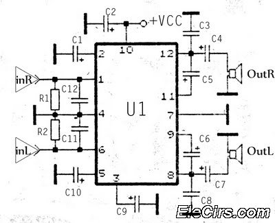
The KA2211 stereo audio power amplifier schematic is designed for electronics applications. This amplifier circuit provides a stereo output with a power output of 2 x 5.8 Watts at an impedance of 4 ohms. The frequency response ranges from...
This amplifier circuit is designed to enhance TV signals in the UHF range. It employs a low-noise transistor, providing an amplification of 10 to 15 dB within the frequency spectrum of 400 MHz to 850 MHz. It is crucial...
The longer the locks remain unused with either the remote or central locking button, the stronger the power surge to the door lock motors. After being activated even once, it seems to drain all the power from the capacitor...
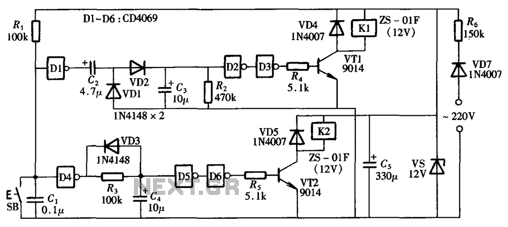
A one-button control switch is designed to control two relays, each of which can switch the load power on and off as needed. The circuit primarily consists of a hex inverter CD4049 and two self-locking DC relays. The circuit utilizes...
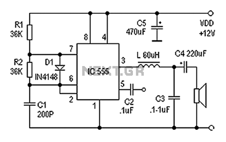
Also known as a digital amplifier, the Class-D amplifier is characterized by its compact size and high efficiency. This circuit utilizes a 555 timer IC to create a Class D amplifier. The 555 timer operates as a controllable multivibrator,...