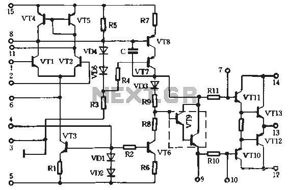
KA2211 Stereo audio power amplifier
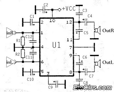
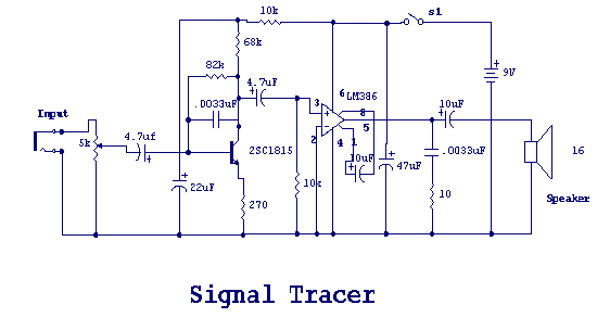
The KA2211 stereo audio power amplifier schematic is designed for electronics applications. This amplifier circuit provides a stereo output with a power output of 2 x 5.8 Watts at an impedance of 4 ohms. The frequency response ranges from 30 Hz to 20 kHz.
The KA2211 stereo audio power amplifier circuit is engineered to deliver robust audio performance suitable for various electronic projects. The design incorporates a dual-channel output configuration, allowing for a total power output of 11.6 Watts, which is ideal for driving speakers in home audio systems or portable devices. The specified impedance of 4 ohms is common for many speaker types, ensuring compatibility with a wide range of audio equipment.
The frequency response of 30 Hz to 20 kHz indicates that the amplifier is capable of reproducing low bass sounds while maintaining clarity in the high-frequency range, making it suitable for diverse audio applications, including music playback and voice amplification. The circuit design typically includes components such as transistors, resistors, capacitors, and a power supply section, which work together to amplify the audio signal effectively.
In practical applications, the KA2211 amplifier can be integrated into various audio devices, enhancing sound output quality. Proper heat dissipation mechanisms should be considered in the design to prevent overheating during prolonged use. Additionally, implementing filtering techniques may improve audio clarity and reduce noise, further enhancing the performance of the amplifier. Overall, the KA2211 is a versatile and efficient choice for audio amplification needs in electronic circuit designs.Circuit KA2211 stereo audio power amplifier schematics Circuit Electronics, This amplifier circuit has a stereo output with a power output of 2 x 5.8 Watt with impedance 4. The frequency response from 30Hz up to 20kHz. amplifier circuit base.. 🔗 External reference
