
Transistor Tester to test Hfe and working of NPN and PNP Transistors

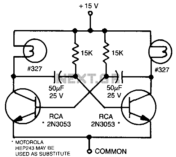
The circuit utilizes a straightforward design to test the hfe of both NPN and PNP transistors effectively. The two constant current sources, Q1 and Q2, are critical components that ensure accurate current flow into the transistors under test. The adjustment of the potentiometers R4 and R5 allows for fine-tuning the constant current to a precise value of 10 µA, which is crucial for reliable hfe measurement.
The operation of the circuit hinges on the principle of transistor switching. During the positive half-cycle of the AC input, Q1 is activated, allowing current to flow through diode D1, lighting the red LED. This visual indication confirms that the NPN transistor is operational. Conversely, during the negative half-cycle, Q2 is activated for the PNP transistor, lighting the green LED when the transistor is functioning correctly.
The inclusion of variable resistors enables the user to test transistors at various base currents, providing flexibility in testing conditions. The circuit's design allows it to identify faulty transistors by observing LED behavior: an open transistor will not conduct, resulting in no LED illumination, while a shorted transistor will cause both LEDs to glow, indicating a closed path.
Overall, this circuit serves as an efficient and effective tool for evaluating the operational status of transistors, making it suitable for educational purposes and practical applications in electronics repair and testing.Here is a very simple circuit that can be used to check the hfe of transistors. Both PNP and NPN transistors can be checked using this circuit. Hfe as high as 1000 can be measured by using this circuit. The circuit is based on two constant current sources build around transistors Q1 and Q2. The Q1 is a PNP transistor and the constant current flows i n the emitter lead. The value of constant current can be given by the equation; (V D1 -0. 6)/ (R2+R4). The POT R4 can be adjusted to get a constant current of 10uA. The Q2 is an NPN transistor and the constant current flows into the collector lead. The value of this constant current can be given by the equation; (VD2-0. 6)/(R3+R5). The POT R5 can be adjusted to get a constant current of 10uA. This constant current provided by the Q1 circuit if the transistor under test is an NPN transistor and by Q2 circuit if the transistor under test is a PNP transistor is fed to the base of transistor under test. This current multiplied by the hfe flows in the collector of the transistor and it will be indicated by the meter.
The meter can be directly calibrated to read the hfe of the transistor. Simple transistor tester is a transistor analyzer circuit which is suitable for testing both NPN and PNP transistors. This is a very simple circuit as compared to other transistor testers. This circuit is very useful for both technicians and students. This circuit can be easily assembled on a general purpose PCB. A basic electronic component like resistors, LED`s, diode and transformer is used for developing this circuit.
Using this circuit, we can check whether a transistor is in good condition or not, is it opened or shorted, and so on. The principle behind this circuit is very simple. This circuit basically works on the basis of transistor switching action (Basic Transistor Theory). Take a look at the circuit diagram given below. During the first half cycle of the transformer input, the emitter base junction of transistor is forward biased and collector base junction is reverse biased and the transistor is in ON state and diode D1 is in forward biased The current starts flow through the D1 and the red LED begins to glow.
During the next half cycle, the transistor is reverse biased and is in OFF state. By the alternative nature of the input AC, we can see that the red LED is in ON state and the transistor is in good working condition(Diode D2 and Green Led is in reverse biased and in OFF state). By using the variable resistor, we can check the transistor with various base currents. If the NPN transistor is in open state, the transistor does not conduct and no current flow through LED.
If the transistor is in shorted condition, the transistor acts as a closed switch. And both diode conduct alternatively and both LED`s starts glowing. The PNP transistor is attached to the device with corresponding pin terminals and switch on the circuit. If, during one half cycle of the input AC (assume top terminal of transformer is negative and bottom is positive), the emitter base and collector base junctions of the transistor are forward biased.
Then, in such a condition if there is a and a current flow through the Diode D2 and the Green LED starts glowing, then understand that the transistor is in good working condition(the Diode D1 and Red LED is in reverse biased and not working at that time). During the next half cycle both diodes, and transistors are reverse biased and in OFF state. By the alternating property of input AC, we feel the Green LED is in ON state. We can check this circuit by providing various base currents (by very the variable resistor. If the PNP transistor is in open state, it doesn`t conduct in both half cycles and no output is obtained.
If the transistor is in a shorted condition, transistor acts as a closed path and both diodes are forward biased alternatively, thus making the two LED`s glow at the same time. 🔗 External reference
Related Circuits
This astable multivibrator utilizes incandescent lamps instead of collector load resistors. The lamps flash on and off alternately. The circuit operates as an astable multivibrator, which is a type of oscillator that continuously switches between its high and low states...
The simplest one-transistor audio mixer circuit diagram available. It utilizes a single transistor and can accommodate multiple audio signals, limited only by the user's budget. BC10. The one-transistor audio mixer circuit is a fundamental design that demonstrates the principles of...

As electrolytic capacitors age, their internal resistance, known as "equivalent series resistance" (ESR), gradually increases, potentially leading to equipment failure. This design allows for the measurement of the ESR of suspect capacitors as well as other small resistances. The...

This device functions as a convenient tool for testing infrared (IR) remote control transmitters used with televisions, VCRs, and similar devices. The IR signals emitted from a remote control are detected by the IR sensor module within the tester,...
This simple circuit tests speakers, microphones, transformers, and voltage. It is essentially a very low-frequency oscillator that produces extremely short "fruity" pulses. The sound produced is easy to hear and allows for precise determination of its direction, making it...
Camping today often requires carrying various electronic devices for daily activities and entertainment. Typically, a charged lead-acid battery and a power inverter are utilized to ensure a well-organized trip, allowing family members to use their electronic devices comfortably. It...