
ESR & Low Resistance Test Meter
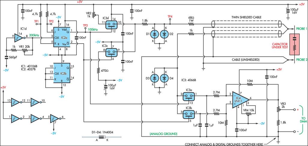
The circuit for measuring the equivalent series resistance (ESR) of electrolytic capacitors is designed to operate efficiently at a frequency of 100 kHz. The oscillator circuit, using inverter IC1d, generates a stable square wave that is then processed by the J-K flip-flop (4027) which ensures a balanced duty cycle for the test signal. The alternating activation of the bilateral switches (4066) allows for the application of the test signal across the capacitor while maintaining a controlled environment to prevent damage from charged capacitors.
The series resistance included in the circuit is critical for limiting the current flowing into the capacitor under test, thereby protecting both the capacitor and the measuring components. The diodes (D1, D2, D3, and D4) play a protective role, ensuring that the signals do not exceed safe levels, which is particularly important when dealing with potentially charged capacitors.
The sample and hold mechanism utilizing the 1 µF capacitors is essential for capturing the average DC level that corresponds to the ESR of the capacitor being tested. This design choice simplifies the measurement process by filtering out AC components, allowing for a clear representation of the ESR on the digital multimeter.
Calibration of the circuit is methodical, requiring adjustments to various variable resistors (VR1, VR2, VR3, and VR4) to ensure accuracy in readings. The procedure includes setting the frequency, ensuring a zero voltage reference, and confirming current flow through the circuit. The final step of adjusting the meter to read the voltage across a known resistor ensures that the system is correctly calibrated for accurate ESR measurement. This comprehensive approach to design and calibration ensures that the circuit remains reliable and effective for testing electrolytic capacitors in various applications.As electrolytic capacitors age, their internal resistance, also known as "equivalent series resistance" (ESR), gradually increases. This can eventually lead to equipment failure. Using this design, you can measure the ESR of suspect capacitors as well as other small resistances. Basically, the circuit generates a low-voltage 100kHz test signal, wh ich is applied to the capacitor via a pair of probes. An op amp then amplifies the voltage dropped across the capacitor`s series resistance and this can be displayed on a standard multimeter. In more detail, inverter IC1d is configured as a 200kHz oscillator. Its output drives a 4027 J-K flipflop, which divides the oscillator signal in half to ensure an equal mark/space ratio.
Two elements of a 4066 quad bilateral switch (IC3c & IC3d) are alternately switched on by the complementary outputs of the J-K flipflop. One switch input (pin 11) is connected to +5V, whereas the other (pin 8) is connected to -5V. The outputs (pins 9 & 10) of these two switches are connected together, with the result being a ±5V 100kHz square wave.
Series resistance is included to current-limit the signal before it is applied to the capacitor under test via a pair of test probes. Diodes D1 and D2 limit the signal swing and protect the 4066 outputs in case the capacitor is charged.
A second pair of leads sense the signal developed across the probe tips. Once again, the signal is limited by diodes (D3 & D4) before begin applied to the remaining two inputs of the 4066 switch (pins 2 & 3 of IC3a & IC3b). These switches direct alternate half cycles to two 1 F capacitors, removing most of the AC component of the signal and providing a simple "sample and hold" mechanism.
The 1 F capacitors charge to a DC level that is proportional to the test capacitor`s ESR. This is differentially amplified by op amp IC4 so that it can be displayed on a digital multimeter 10 © will be represented by 100mV, 1 © by 10mV, etc. To calibrate the circuit, first adjust VR1 to obtain 100kHz at TP3. Next, momentarily short the test probes together and adjust VR4 for 0mV at pin 6 of IC4. That done, set your meter to read milliamps and connect it between TP4 and the negative (-) DMM output.
Apply -5V to TP2 and note the current flow, which should be around 2. 1mA. Transfer the -5V from TP2 to TP1 and adjust VR2 until the same current (ignore sign) is obtained. Remove the -5V from TP1. Again, set to your meter to read volts and connect it to the DMM outputs. Apply the probes to a 10W resistor and adjust VR3 for a reading of 100mV. Finally, ensure that all capacitors to be tested are always fully discharged before connecting the probes. 🔗 External reference
Related Circuits
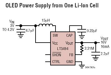
The LT3494 and LT3494A are low-noise boost converters that integrate a power switch, Schottky diode, and output disconnect circuitry. These devices utilize an innovative control technique that results in minimal output voltage ripple and high efficiency across a broad...
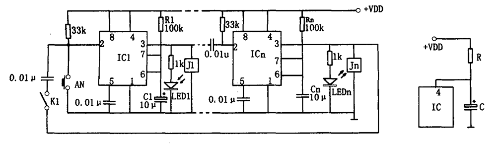
The multi-channel temperature measurement circuit is illustrated in the figure. The core of the test circuit comprises a 555 one-shot delay circuit. When the button is pressed, the output pin of the 555 timer (IC1) goes high due to...
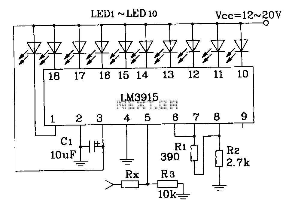
This document describes a simple LM3915 audio power meter circuit diagram. It notes that if the internal resistance of the speaker is 4 ohms, a resistor value of 10k ohms should be used for Rx. For an 8-ohm speaker,...
This sound level meter serves as an effective one-chip replacement for standard analog meters. It is entirely solid-state, ensuring durability and longevity. The circuit is built around the LM3915 audio level integrated circuit (IC) and requires only a minimal...
The Testatika design based on the Pidgeon/Wimshurst machine is of course only one type of electrostatic generator to build this system around. Since the early 1900s such power generators have come a long way in sophistication - and in...
Two single-ended circuits are connected back to back to provide a differential input. This circuit not only features a differential input but also exhibits high impedance, significantly higher than that of an analog ammeter without this circuit. A schematic...
Warning: include(partials/cookie-banner.php): Failed to open stream: Permission denied in /var/www/html/nextgr/view-circuit.php on line 713
Warning: include(): Failed opening 'partials/cookie-banner.php' for inclusion (include_path='.:/usr/share/php') in /var/www/html/nextgr/view-circuit.php on line 713