
Transistor Testers
The circuit utilizes a 555 timer configured in astable mode to generate a square wave output at a frequency of 12 Hz. This frequency is suitable for visual testing of transistors, as it provides a clear indication of the transistor's state through the blinking of the LEDs. The 4027 flip-flop serves as a frequency divider, effectively halving the frequency of the input signal, which results in complementary outputs at pins 14 and 15. These outputs are responsible for driving the two LEDs, which are crucial for visual feedback during testing.
The current-limiting resistor R3 is essential to prevent excessive current from flowing through the LEDs, thus protecting them from damage. The arrangement of the LEDs is such that they are oriented in opposite directions, allowing them to indicate the polarity of the voltage applied across the transistor being tested. This configuration provides a straightforward method for determining whether the transistor is functioning correctly.
Resistors R4 and R5 play a critical role in biasing the transistor under test. When a transistor is connected, it will either allow or block current flow based on its type (NPN or PNP) and condition. A properly functioning NPN transistor will conduct when a positive voltage is applied to its base, allowing current to flow through LED1, causing it to light up. Conversely, a good PNP transistor will conduct when a negative voltage is applied to its base, resulting in LED2 lighting up.
In the case of an open transistor, the lack of conduction will cause both LEDs to flash, indicating that the transistor is not functioning. If the transistor is shorted, the circuit will not allow current to flow through either LED, resulting in no illumination. This simple yet effective circuit provides a reliable means of testing transistors, making it a valuable tool for electronics enthusiasts and professionals alike.This simple circuit has helped me out on many occasions. It is able to check transistors, in the circuit, down to 40 ohms across the collector-base or base-emitter junctions. It can also check the output power transistors on amplifier circuits. Circuit operation is as follows. The 555 timer ( IC1 ) is set up as a 12hz multi vibrator. The output on pin 3 drives the 4027 flip-flop (IC2). This flip-flop divides the input frequency by two and delivers complementary voltage outputs to pin 15 and 14. The outputs are connected to LED1 and LED2 through the current limiting resistor R3. The LED`s are arranged so that when the polarity across the circuit is one way only one LED will light and when the polarity reverses the other LED will light, therefore when no transistor is connected to the tester the LED`s will alternately flash.
The IC2 outputs are also connected to resistors R4 and R5 with the junction of these two resistors connected to the base of the transistor being tested. With a good transistor connected to the tester, the transistor will turn on and produce a short across the LED pair.
If a good NPN transistor is connected then LED1 will flash by itself and if a good PNP transistor is connected then LED2 will flash by itself. If the transistor is open both LED`s will flash and if the transistor is shorted then neither LED will flash.
🔗 External reference
Related Circuits
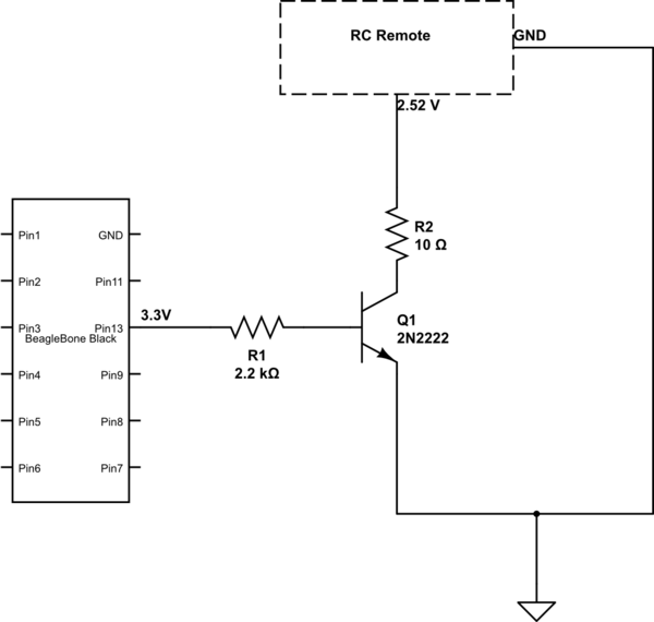
The remote control of an RC car was modified by extending wires from the backward, forward, left, and right switches. Grounding any of these wires completes the circuit and sends a signal to the car. The intention is to...
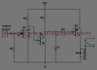
This document describes a series of touch switches that utilize only three transistors. These touch-based transistor switches can activate a load simply by the user touching a metal plate. They are designed to directly switch a relay, enabling operation...
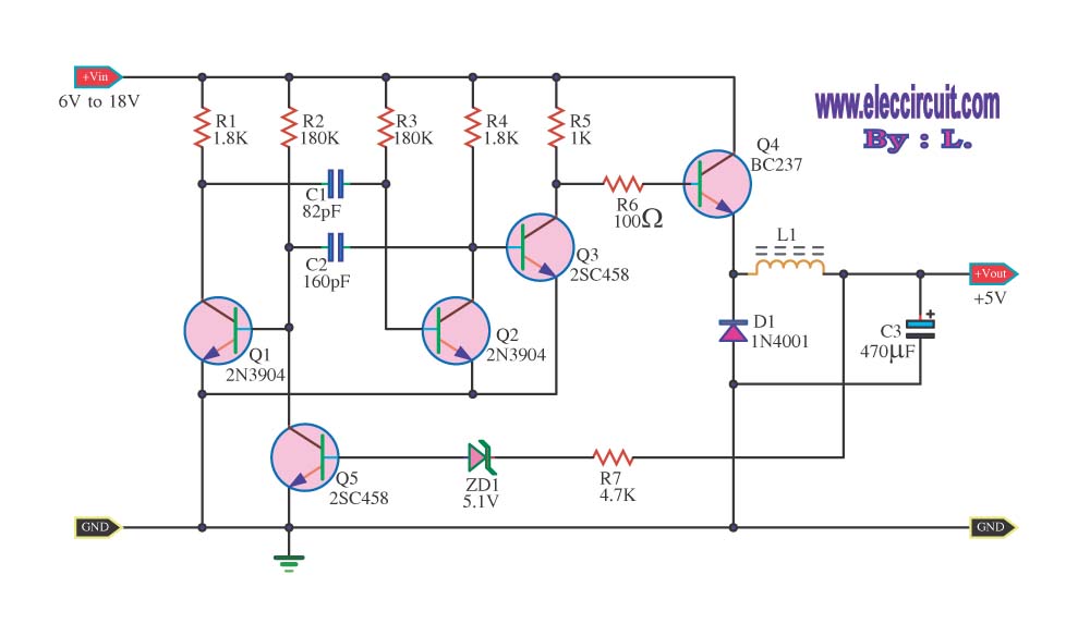
The circuit reduces voltage size or functions as a step-down voltage converter circuit, specifically a DC regulated circuit model using a switching converter. It generates the desired voltage output. The step-down voltage converter circuit, also known as a buck converter,...

This is a Class AB transistor power amplifier. It is straightforward to construct, utilizing standard components, and is known for its stability and reliability. The entire circuit employs commonly available parts and can be easily assembled on a general-purpose...
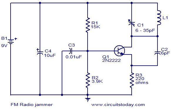
This circuit can be utilized to jam FM radios in its vicinity. It is a classic single transistor oscillator operating in the VHF region. The working principle of the circuit is straightforward. Powerful VHF oscillations generated by the circuit...

Both circuits can synchronize trapezoidal wave voltage, which is converted into intermittent small rectangular pulses. Its working principle involves periodic operation in synchronization with the grid frequency of the zero-volt switching voltage of the DC chopper. Due to the...