
FM Radio Jammer With 2N2222 Transistor
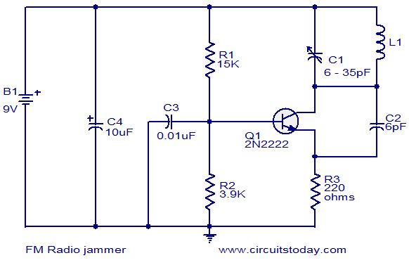
The described circuit is designed as a VHF oscillator, primarily using a 2N2222 NPN transistor, which serves as the active amplification component. The circuit operates by generating oscillations in the VHF frequency range, typically between 30 MHz and 300 MHz, which is the standard operational band for FM radio transmissions.
The configuration of the circuit includes a feedback loop that stabilizes the oscillation frequency. The inductor and capacitor form a resonant LC circuit, which determines the oscillation frequency. The resistor is used to set the biasing conditions of the transistor, ensuring it operates in the active region for optimal performance.
Power for the circuit is supplied by a battery, which provides the necessary voltage and current for the transistor to function effectively. The output of the oscillator is coupled to the antenna, which radiates the VHF signals. These signals interfere with nearby FM radio frequencies, effectively jamming the reception of legitimate broadcasts.
Due to the nature of this circuit, it is important to note that the use of jamming devices may be illegal in many jurisdictions, as they can disrupt legitimate communications and violate regulations set forth by telecommunications authorities. Therefore, this circuit should be used with caution and awareness of local laws regarding radio frequency interference.This Circuit can be used to jam FM radios in its vicinity. This is a classic single transistor oscillator operating in the VHF region. Working principle of the circuit is very simple and straight forward. Powerful VHF oscillations from the circuit will interfere with the FM signals to nullify it. Component: 2N2222 Transistor, Resistor , Capacitor, Battery, Inductor. [circuitstoday. com] 🔗 External reference
Related Circuits
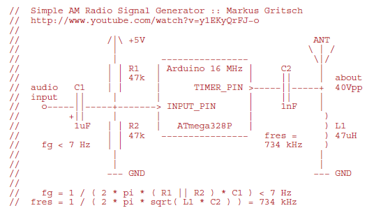
Markus constructed a software AM radio transmitter utilizing an Arduino. The audio signal is supplied to the ADC input via a decoupling capacitor. A PWM output pin directly controls a capacitor-inductor circuit connected to an antenna. The schematic and...
Figure 2-33 (a) illustrates the schematic diagram of a robot approaching an object. When no objects are detected in front of the robot, it moves forward in a straight line. If an object is detected on the left or...
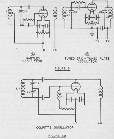
The tuned circuits of capacitance and inductance used in vacuum tube transmitter circuits are often referred to as "tank" circuits, as they serve as reservoirs of RF energy. Blocking capacitors are employed to create a high impedance path for...
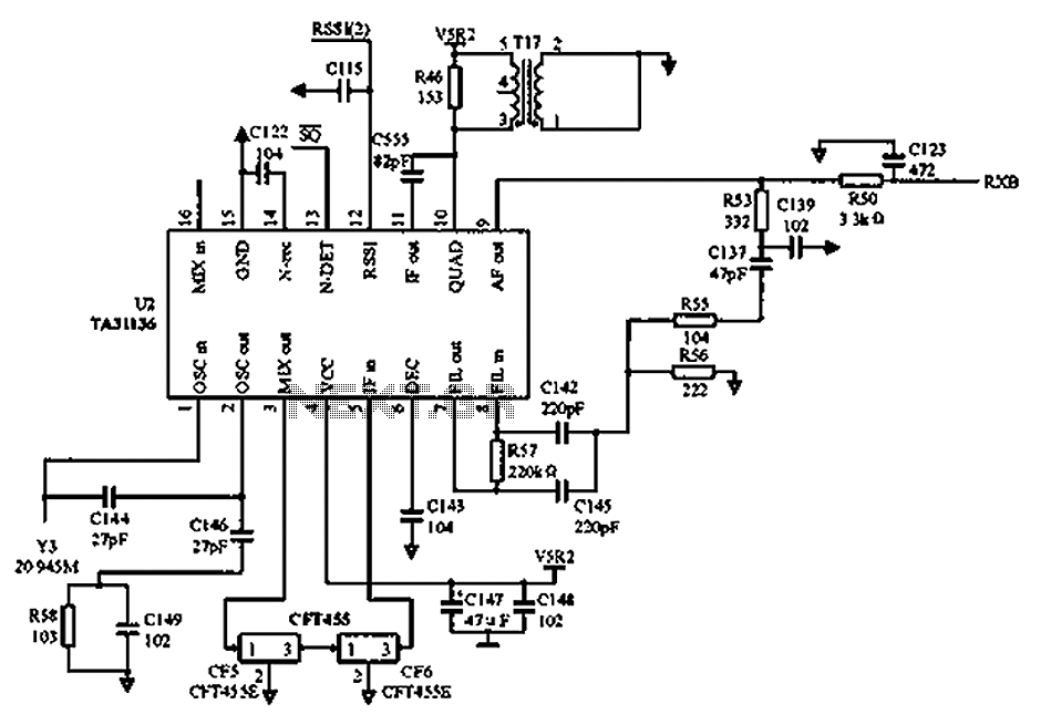
As illustrated in the figure, Vcc is the power supply for the circuit. Upon receiving the initial signal, the frequency is adjusted to 21.7 MHz. This frequency is subsequently enhanced through two crystal filters to improve the selectivity of...
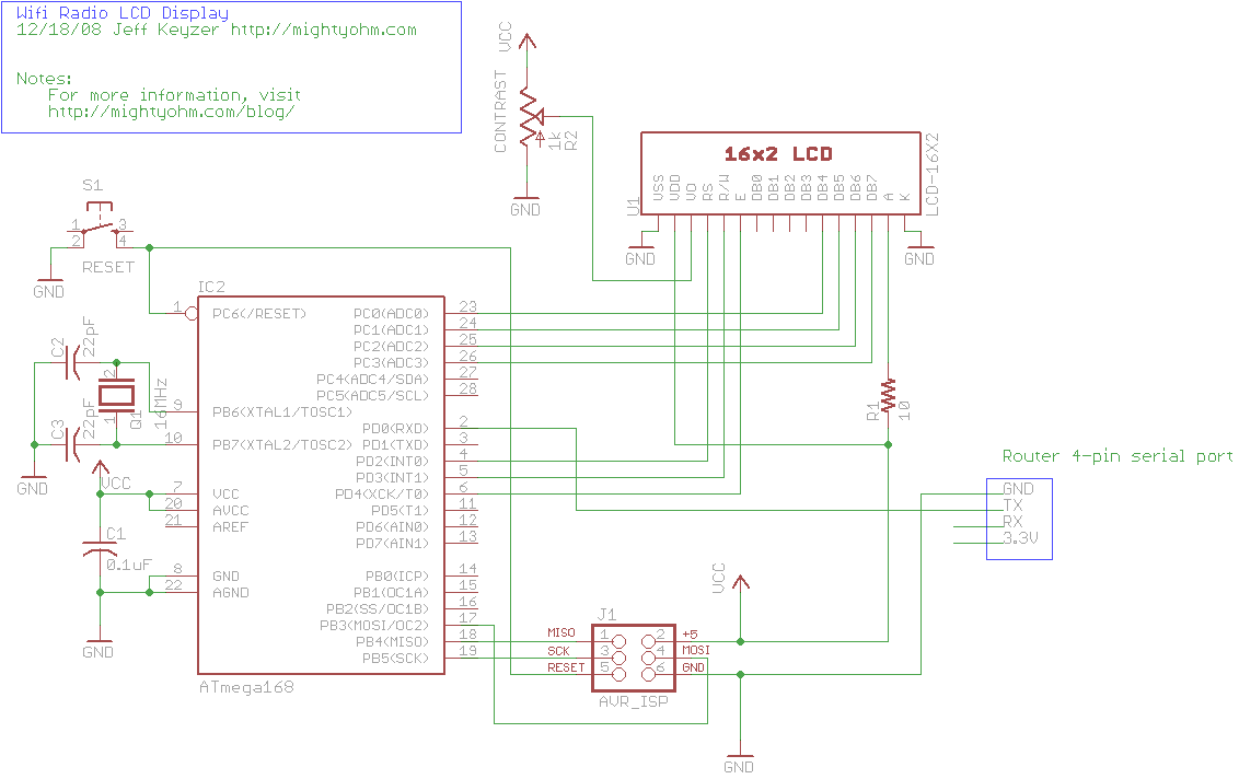
This is the seventh part of an ongoing series about building a low-cost, open-source streaming internet radio. If you have not already, check out the previous parts for some background about the project. In part six, UNIX-style shell commands...
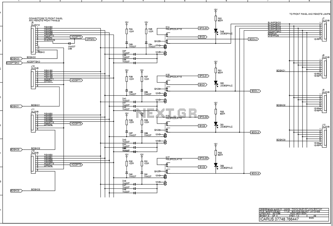
The main box of the Transmit Selector system is designed to be located in the technical rack of a small radio broadcast station. There are four stereo balanced line inputs, either of which can be routed to a stereo...