
Transistor Turns Op Amp On Or Off
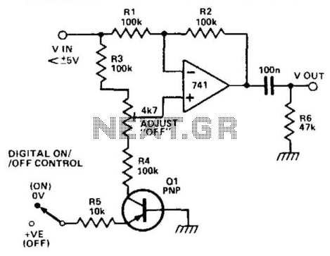
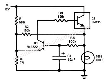
In this circuit configuration, the operation of transistor Q1 is critical in determining the behavior of the overall system. When Q1 is off, it allows the circuit to function as a voltage follower, which is characterized by its ability to provide a high input impedance and a low output impedance. This configuration is beneficial for buffering signals, as it prevents loading effects on the preceding stage.
Upon applying a positive voltage to the emitter of Q1 via the 10 kΩ resistor, the transistor enters saturation, effectively pulling the lower end of resistor R4 to ground. This action alters the circuit's dynamics, but it is essential to note that the configuration remains stable, maintaining a voltage difference of 0 V across the operational amplifier's input terminals. The operational amplifier, in this case, is configured to operate in a differential mode, but due to the balanced resistor ratios in the two branches, the output remains at zero volts.
The inclusion of the 47 kΩ resistor serves a crucial role in nullifying any potential discrepancies in the resistor ratios. This adjustment is vital for maintaining the desired performance characteristics, particularly ensuring that the off attenuation remains above 60 dB. The high common-mode rejection ratio (CMRR) of the 741 operational amplifier is instrumental in achieving this level of attenuation. CMRR quantifies the amplifier's ability to reject common-mode signals, which is particularly advantageous in applications where noise and interference may be present.
Overall, this circuit exemplifies the principles of transistor operation and operational amplifier functionality, highlighting the importance of component selection and configuration in achieving desired electrical characteristics. When transistor Q1 is switched off, the circuit behaves as a voltage follower. By applying a positive vol tage to the emitter of Q1 via a 10 KOhmhm resistor, the transistor is made to turn on and go into saturation. Thus, the lower end of R4 is connected to ground. The circuit has not changed into that of a differential amplifier, except that the voltage difference is always 0 V.
As long as the resistor ratios in the two branches around the op amp are in the same ratio, the output should be zero. A 47-KOhm resistor is used to null out any ratio errors so that the off attenuation is more than 60 dB.
The high common-mode rejection ratio of a 741 enables this large attenuation to be obtained. 🔗 External reference
Related Circuits
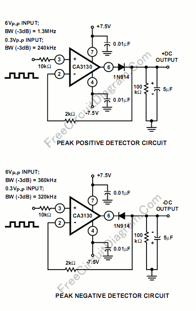
Implementing peak-detector circuits is straightforward with the CA3130, as illustrated in the schematic diagram of this circuit. The figure below presents the schematic diagram. The CA3130 is a high-performance operational amplifier that is well-suited for peak detection applications due to...

This circuit was designed to provide that continuous light lamps already wired into a circuit become flashing. Simply insert the circuit between existing lamp and negative supply. Especially suited for car or panel pilot lights, this device can drive...
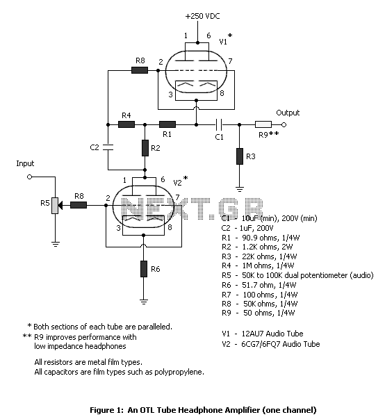
The tube headphone amplifier in figure 1 is a high current mu follower, with a 12AU7 cathode follower driven by a 6CG7. Both sections of each tube are paralleled to minimize noise. It's a zero global feedback, OTL design...
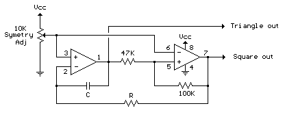
The circuit illustrates a straightforward triangle and square wave generator utilizing a common dual operational amplifier, the LM1558, capable of producing very low frequencies around 10 kHz. The time interval for one half-cycle is approximately determined by the product...
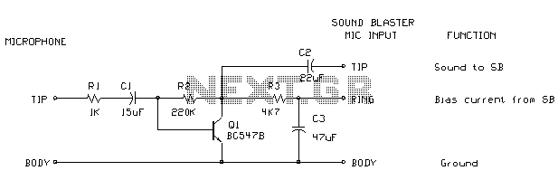
Soundblaster soundcard series (SB16, SB32, AWE32 and AWE64) have all a microphone input designed to be used with the electret microphones which come with the soundcard package (some packages) or with separate microphone designed to be used with SoundBlaster...
This circuit is a series of electric lamp flashers. It is designed to flash a 12V bulb approximately once per second. The configuration allows Q2 and Q1 to provide biasing, eliminating the need for a resistor. Typically, a cold...
Warning: include(partials/cookie-banner.php): Failed to open stream: Permission denied in /var/www/html/nextgr/view-circuit.php on line 713
Warning: include(): Failed opening 'partials/cookie-banner.php' for inclusion (include_path='.:/usr/share/php') in /var/www/html/nextgr/view-circuit.php on line 713