
Transistored 10W Audio Amplifier
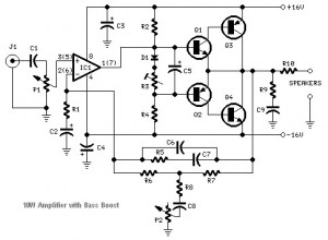
This audio amplifier circuit employs the NE5532 operational amplifier, known for its low noise and high performance, making it suitable for audio applications. The TIP41A and TIP42A power transistors are configured in a push-pull arrangement, which enhances the circuit's efficiency and output power capabilities. The design allows for a maximum output of 10W into an 8-ohm load, making it suitable for driving small loudspeakers effectively.
The inclusion of a bass-boost control in the feedback loop addresses the inherent limitations of the amplifier concerning low-frequency response. By allowing for an increase of up to +16.4dB at 50Hz, the circuit compensates for the typical roll-off that occurs in small speaker systems. This adjustment ensures a more balanced audio output, particularly for bass-heavy music genres.
To maintain optimal performance, careful attention must be paid to the grounding scheme. The ground connections for various components, including the input and output stages, should be unified at a single point to minimize ground loops and hum. This practice is crucial in audio applications where noise can significantly impact sound quality.
The circuit's design thus balances performance and usability, making it an excellent choice for audio enthusiasts seeking a compact and effective amplifier solution.Build based operational amplifier NE5532 and a couple of power transistor TIP41A / TIP42A, this audio amplifier circuit has capability to deliver up to 10W audio power output into 8 ohm speaker. This circuit is related to the 18 Watt Audio Amplifier, and was designed mainly to satisfy the requests of correspondents unable to locate the TLE2141C c
hip. It works with the widespread NE5532 Dual IC but, certainly, its capability output is going to be comprised around the 9. 5 11. 5W range, because the voltage supply rails can not exceed ±18V. As amplifiers of this variety are usually applied to drive small loudspeaker cabinets, the bass frequency range is rather sacrificed.
As a result a bass-boost manage was inserted within the feedback loop of the amplifier, so as to overcome this issue with out top quality losses. The bass lift curve can reach a maximum of +16. 4dB @ 50Hz. In any case, even when the bass manage is rotated totally counterclockwise, the amplifier frequency response shows a gentle raising curve: +0.
8dB @ 400Hz, +4. 7dB @ 100Hz and +6dB @ 50Hz (referred to 1KHz). A right grounding is extremely necessary to eradicate hum and ground loops. Connect for the identical point the ground sides of J1, P1, C2, C3 &C4. Connect C9 towards the output ground. Then connect separately the input and output grounds to the power supply ground. 🔗 External reference
Related Circuits
This preamplifier was designed to cope with CD players, tuners, tape recorders etc., providing a gain of 4, in order to drive less sensitive power amplifiers. As modern Hi-Fi home equipment is frequently fitted with small loudspeaker cabinets, the...
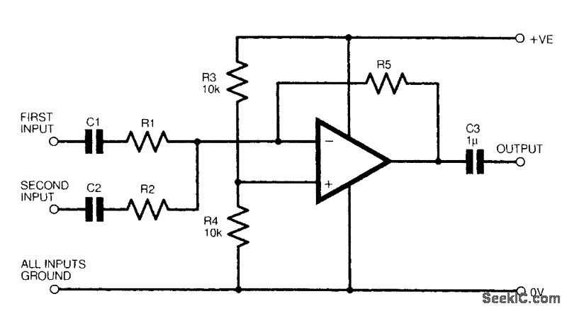
The figure illustrates a fundamental two-channel operational amplifier (op-amp) mixer circuit. The gain for channel 1 is determined by the ratio of resistors R5 to R1, while for channel 2, it is determined by the ratio of R5 to...
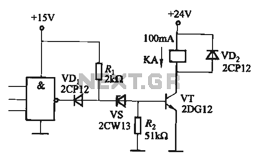
If the CMOS circuit load (actuator) is a relay device, the circuit must have a large load capacity. Non-gate drive switching amplifiers are connected to a separate element shown in the interface circuit. In the context of a CMOS circuit...
Many a times one needs an extra telephone ringer in an adjoining room to know if there is an incoming call. For example, if the telephone is installed in the drawing room you may need an extra ringer in...
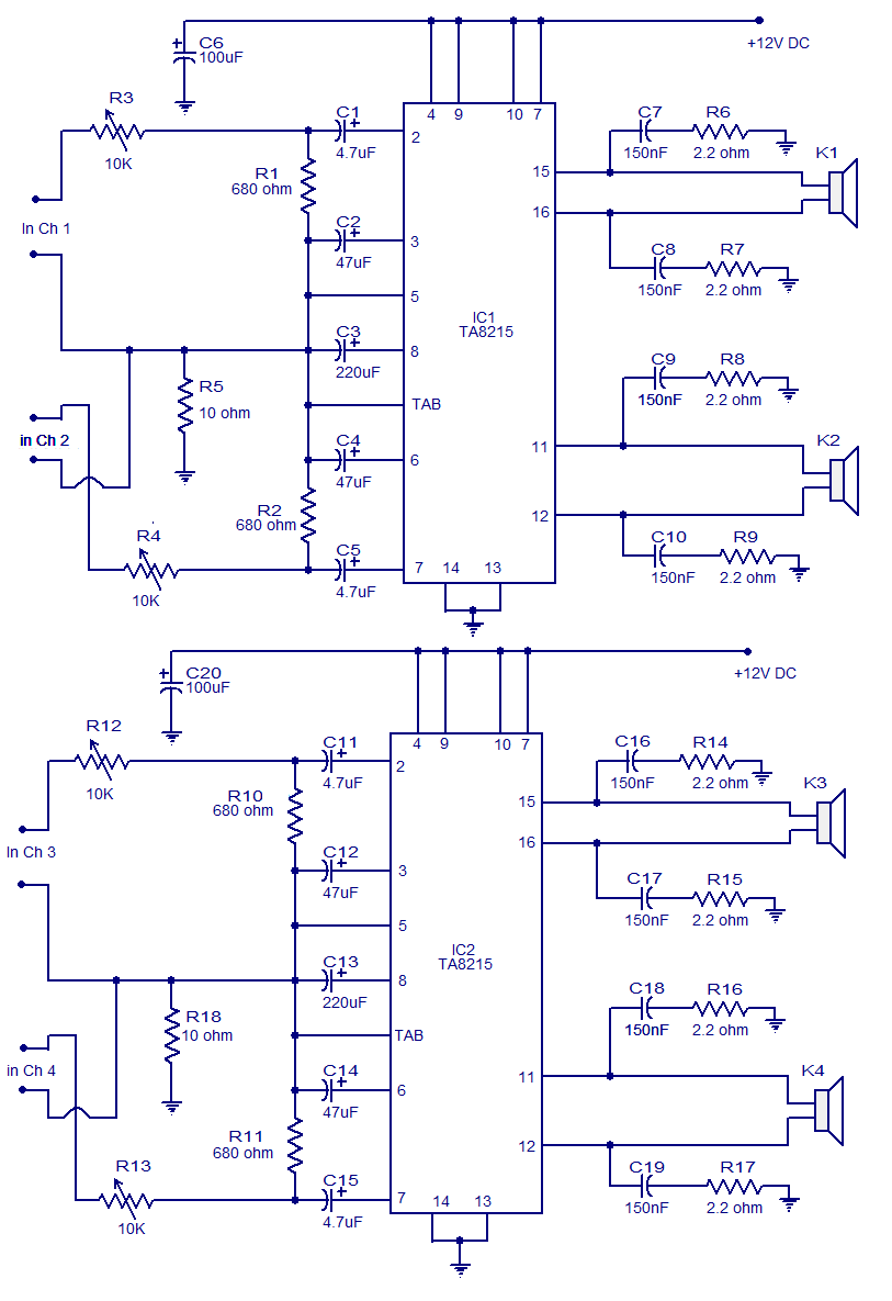
Many electronic circuits related to audio amplifiers have been published. This particular circuit is unique as it is a four-channel amplifier. Each channel can deliver an output of 15 watts into a 4-ohm speaker. The amplifier operates from a...
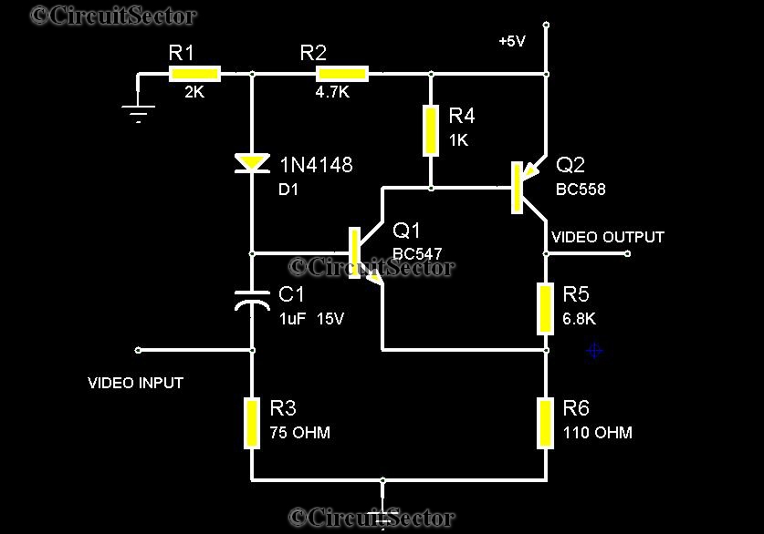
There are instances when it is necessary to view video clips captured by a digital camera on a television. This can be accomplished by connecting the camera's video output to the television's video input. However, a direct connection is...