
Transistorized Bar-Graph Driver
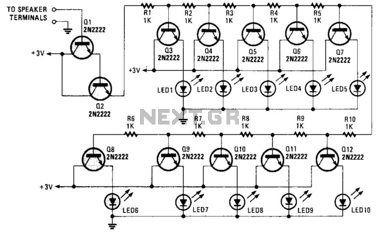
The circuit comprises a series of resistors (R1 to R10) forming a network that serves as a voltage divider, providing appropriate biasing levels for the transistor emitters. The emitter followers (Q1 and Q2), typically configured as bipolar junction transistors (BJTs), are used to buffer the voltage from the resistor network. This configuration allows for high input impedance and low output impedance, ensuring minimal loading on the preceding stage while effectively driving the LED drivers (Q3 through Q7).
The LED drivers are responsible for illuminating the LEDs in accordance with the audio signal levels. As the audio signal amplitude varies, the voltage across the resistor network changes, which in turn modulates the base voltage of the emitter followers. The output from the emitters of Q1 and Q2 is then fed into the bases of Q3 through Q7, which are configured to drive the LEDs. This arrangement allows the circuit to produce a visual representation of the audio signal's volume, effectively creating a "light organ" effect.
The circuit can be connected to various audio sources, including speakers or direct audio outputs from devices, making it versatile for different applications. The design ensures that the LEDs illuminate in a manner proportional to the audio input, providing an intuitive visual feedback mechanism for users. The use of multiple LED drivers allows for a more dynamic and visually appealing display, as different LEDs can light up at varying intensities based on the audio signal's characteristics. A resistor network (Rl through RIO) with emitter followers (Ql and Q2) drives LED drivers (Q3 through Q7). This circuit was used as a "light organ" to provide visual volume indication. It can be hooked to a speaker, to another audio source, etc. 🔗 External reference
Related Circuits
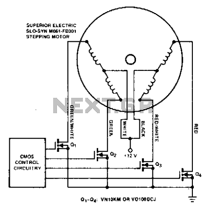
Stepping motors are commonly utilized in disk drives and machine control applications. MOSPOWER transistors serve as excellent motor drivers due to their immunity to second breakdown. It is important to note that snubbing networks are unnecessary since load line...
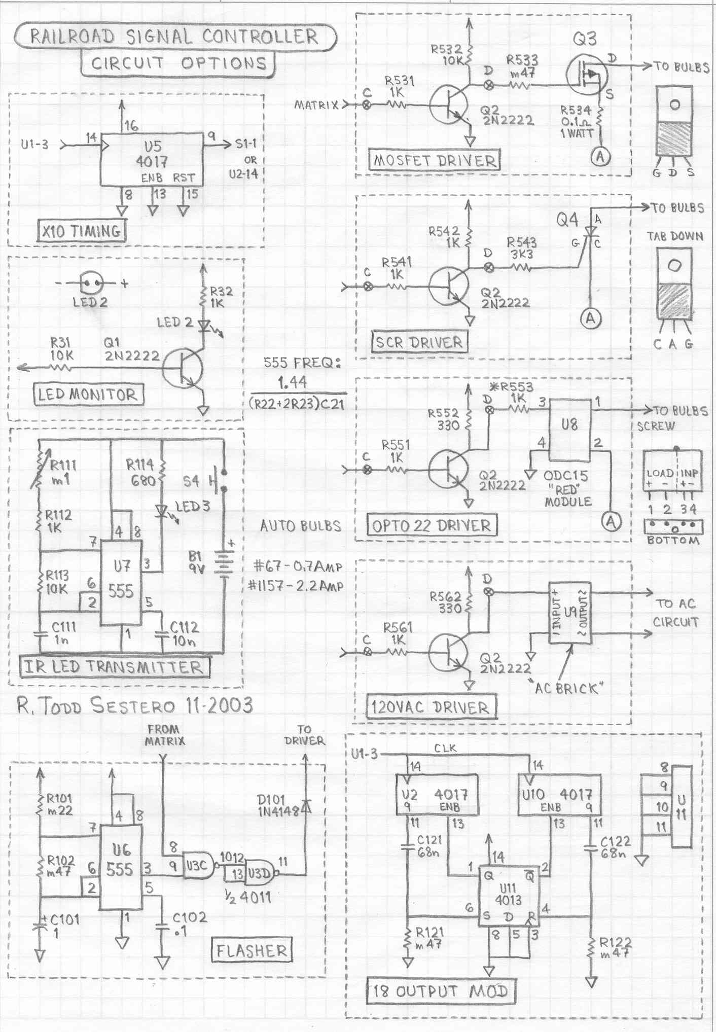
This circuit is designed to illuminate a single prototype railroad signal. It can be utilized for driving a model railroad signal, but it is intended solely for static displays and is not compatible with DCC systems, computers, or similar...
The converter utilizes a TinySwitch-III family member (U2, a TNY279PN) to deliver up to 1.8 A of load current to six high-intensity Luxeon LEDs (LXHL series). The output voltage is slightly below the forward voltage drop of the LEDs,...
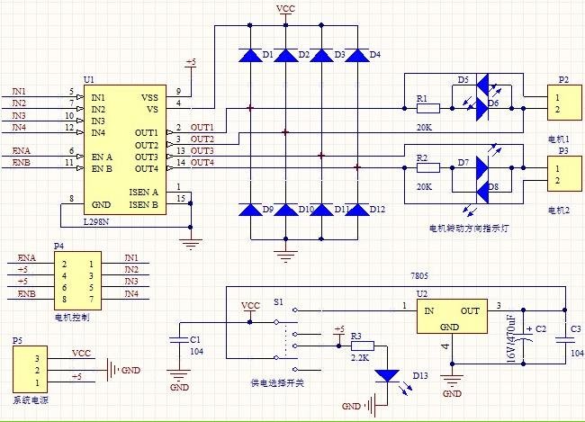
1. Driver: L298N Dual H Bridge DC Motor Driver IC 2. Supply voltage for the driven part (Vs): +5 V to +35 V; for internal board power supply, Vs: +7 V to +35 V 3. Peak current for the...
Depending on its design, an electric guitar may have anywhere from one to six pickup elements. Classic acoustic guitars can also benefit from one or more retrofitted pickups. Each pickup produces a specific sound based on the type of...

A solid-state flyback driver based on a micro solid-state Tesla coil circuit created by Steve Ward. The schematic is reprinted here with credits to Steve Ward. Instead of an air-core Tesla Coil setup, a flyback transformer is utilized. An...
Warning: include(partials/cookie-banner.php): Failed to open stream: Permission denied in /var/www/html/nextgr/view-circuit.php on line 713
Warning: include(): Failed opening 'partials/cookie-banner.php' for inclusion (include_path='.:/usr/share/php') in /var/www/html/nextgr/view-circuit.php on line 713