
transistors Can someone help me understand this H-Bridge

The H-Bridge is a crucial component in controlling the direction and speed of a DC motor, which is typically used in RC cars for propulsion. It allows the voltage to be applied across the motor terminals in either direction, enabling forward and reverse motion. Understanding the operation of the H-Bridge is essential for integrating it with the custom-built receiver and transmitter.
An H-Bridge typically consists of four switches (transistors or MOSFETs) arranged in a configuration that can control the voltage across the motor. The basic operation involves the following states:
1. **Forward Motion**: To drive the motor forward, switches Q1 and Q4 are turned on, while Q2 and Q3 remain off. This configuration allows current to flow through the motor in one direction.
2. **Reverse Motion**: To reverse the motor's direction, switches Q2 and Q3 are activated, while Q1 and Q4 are turned off. This change in switch states reverses the current flow through the motor.
3. **Braking**: To stop the motor quickly, both pairs of switches (Q1 & Q2 or Q3 & Q4) can be turned on simultaneously, creating a short circuit across the motor terminals.
4. **Coasting**: All switches can be turned off, allowing the motor to coast to a stop with no active braking.
When integrating the H-Bridge with the microcontroller and the 2.4 GHz transceiver, it is important to ensure that the control signals from the microcontroller are compatible with the H-Bridge's input requirements. The microcontroller can be programmed to send PWM signals for speed control and digital signals for direction control based on the commands received from the transceiver.
To implement this, the microcontroller's GPIO pins can be connected to the control inputs of the H-Bridge. The transceiver will receive the control commands from the user and transmit them to the microcontroller, which will then interpret these commands and activate the appropriate switches in the H-Bridge.
In summary, understanding the H-Bridge's operation is vital for successful integration with the custom Rx/Tx system. Proper configuration and control of the H-Bridge will enable the RC car to operate as intended, with both forward and reverse motion capabilities, as well as speed control.An old RC car but without the transmitter so I built my own Rx/Tx using MCU and 2. 4Ghz transceiver, however, I want to use the car`s original H-Bridge but not sure if I understood how that circuit works. 🔗 External reference
Related Circuits
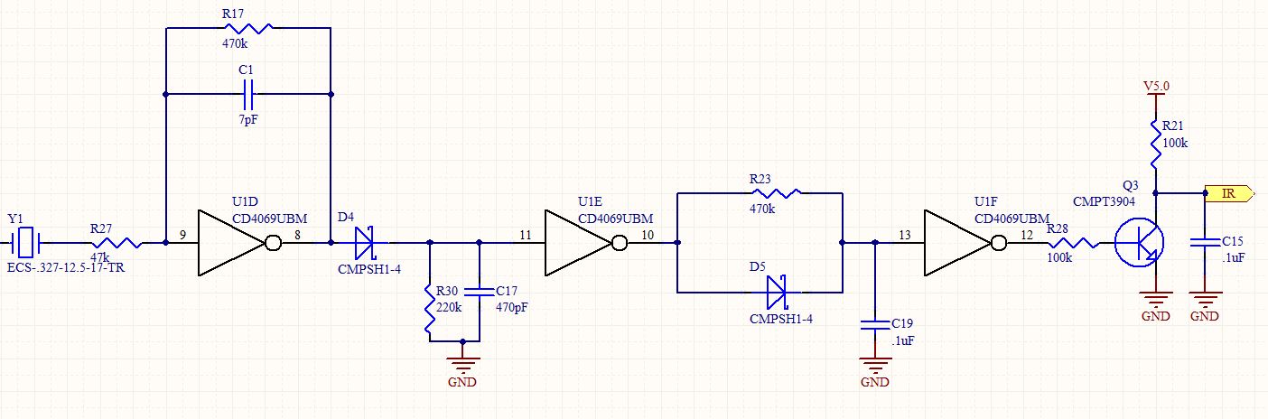
This is a follow-up to an earlier post regarding a specific circuit schematic. The circuit is designed to operate at a supply voltage of 5V, and testing has confirmed that the original device functions correctly at this voltage. A...
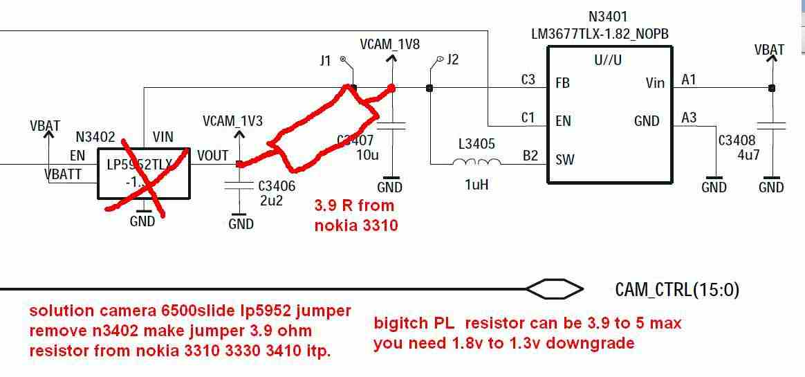
The Nokia 6500 camera issue, characterized by messages such as "camera operation failed" or a blank camera display, can potentially be resolved through a simple workaround. The accompanying images illustrate the Nokia 6500 slide camera problem and suggest creating...
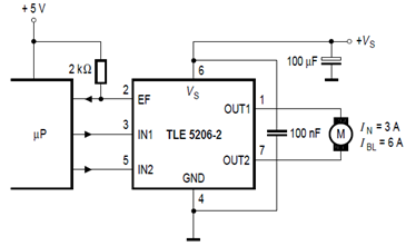
The schematic below illustrates the TLE5206-2 5A H-Bridge circuit for DC motor applications. This device features an integrated power H-bridge with DMOS output stages designed specifically for driving DC motors, as indicated in the datasheet. The TLE5206-2 circuit application...
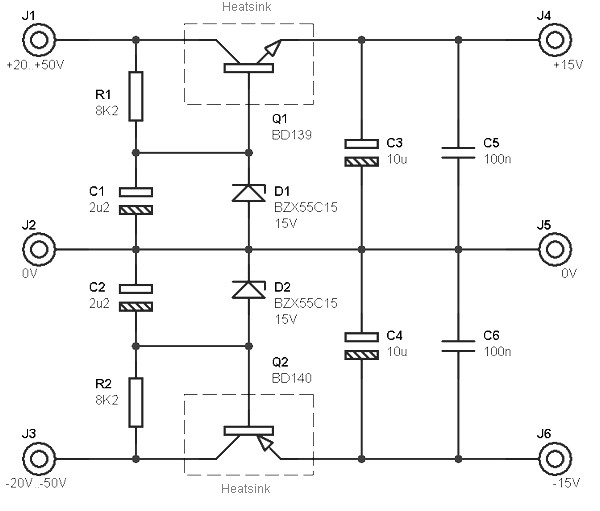
This circuit is designed to be integrated into an existing circuit, such as an audio amplifier, which already supplies symmetric voltages of +20V/-20V and +50V/-50V. The schematic diagram is derived from a dual polarity power supply circuit providing +/-...
The Triac drivers utilize the 5 VDC output signal from the 74HC595 chip outputs (Q1, Q2, Q3, Q4, Q5, Q6, and Q7) to control the 110VAC gate signal to the Triacs. When connecting the integrated circuits (ICs) directly to...
Several individuals have mentioned that the house number is difficult to read at night. The number comprises four digits mounted on a structural column that supports a section of the roof. In response to these concerns, a request has...